
Upright-Plate Type Sunlight Generator

a solar photovoltaic and generator technology, applied in the safety of solar heat collectors, machines/engines, light and heating equipment, etc., can solve the problems of low efficiency limited commercial application and low cost of solar photovoltaic power generation systems, so as to reduce system cost, save pv cell consumption, and high concentration

Inactive Publication Date: 2009-07-09
WANG CUNYI
View PDF5 Cites 13 Cited by
  • Summary
  • Abstract
  • Description
  • Claims
  • Application Information

AI Technical Summary

Benefits of technology

[0012]In order to solve the problems described above, the present invention provides a new solar PV power generating technology which can realize automotive sunlight tracking and high concentration photovoltaic power generation, so as to save the PV cells consumption and decrease the system cost, and make the sunlight even; at same time not only high effectively utilize the direct sunlight and the diffuse light, but also realize the medium concentration PV power generation and decrease the working temperature of the solar cells under the environment temperature; and automatically clean the dust and snow to overcome the “heat island effect” which will damage the efficiency of the PV cells and the use life of the solar PV power generating system.
[0013]This invention combine the wind and solar PV power generating systems in order to decrease the cost of solar PV power generating system (e.g., controller, solar power generation converser, accumulator, inverter etc.), and make the solar power supply consistently.

Problems solved by technology

However, the cost in the PV industry is relatively high, and the solar PV power generation still limits the commercial application though some achievements have been got.
Firstly, most of solar PV power generating systems are in fixed state and work only 4 hours at peak even in a good whether condition, which is a waste to the solar PV power generation.
After deducting the cost of automatic sun-tracking machine, the solar PV power generating system cost can only be decreased around 20%, which is nothing to improve the photoelectric conversion efficiency.
Thirdly, people try to use the high multiple light collecting technology and automatic sun-tracking to improve the conversion efficiency and decrease the cost, the above problems can be solved by this method but some new problems will happen:1. the high multiple light collecting can only focus direct light, but not diffuse light;2. the high temperature caused by the high multiple light collecting may decrease the efficiency of photoelectric conversion and shorten the use life of PV cells;3. the non-planar mirrors used in the high multiple light collecting may cause the sunlight uneven, damage PV cells and decrease the conversion efficiency.
If we can solve the latter two problems described above, the high multiple light collecting will highly increase PV system efficiency and decrease the cost of PV cells in the rich direct solar light area, but the efficiency will be worse in the rich solar diffuse light area and to make the uneven solar light even after using the high multiple light collecting will increase the cost.
In addition, the present of “heat island effect” in current solar PV power generating system will decrease the efficiency of photoelectric conversion and the use life of PV cells.
This is, when the solar PV system is exposed to the sunlight, the guano, leaves etc. stacking on the PV panel make the sunlight uneven, and the dust, dirty marks and snow in winter on the cells make the sunlight hitting proportion decrease and affect the efficiency of PV system.

Method used


Image

  • Upright-Plate Type Sunlight Generator
  • Upright-Plate Type Sunlight Generator
  • Upright-Plate Type Sunlight Generator

Examples


Embodiment Construction

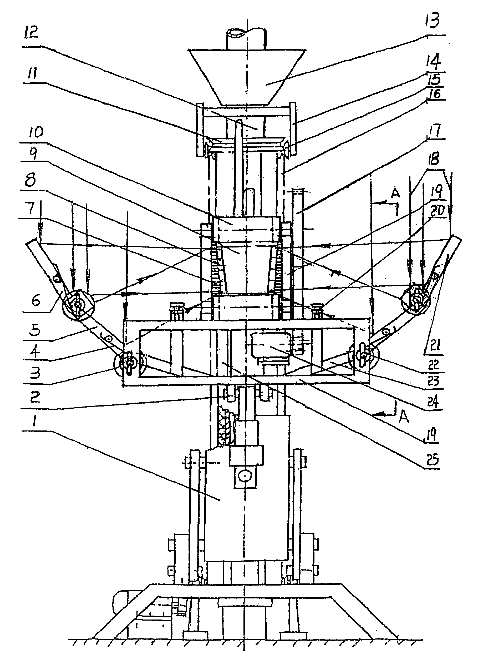
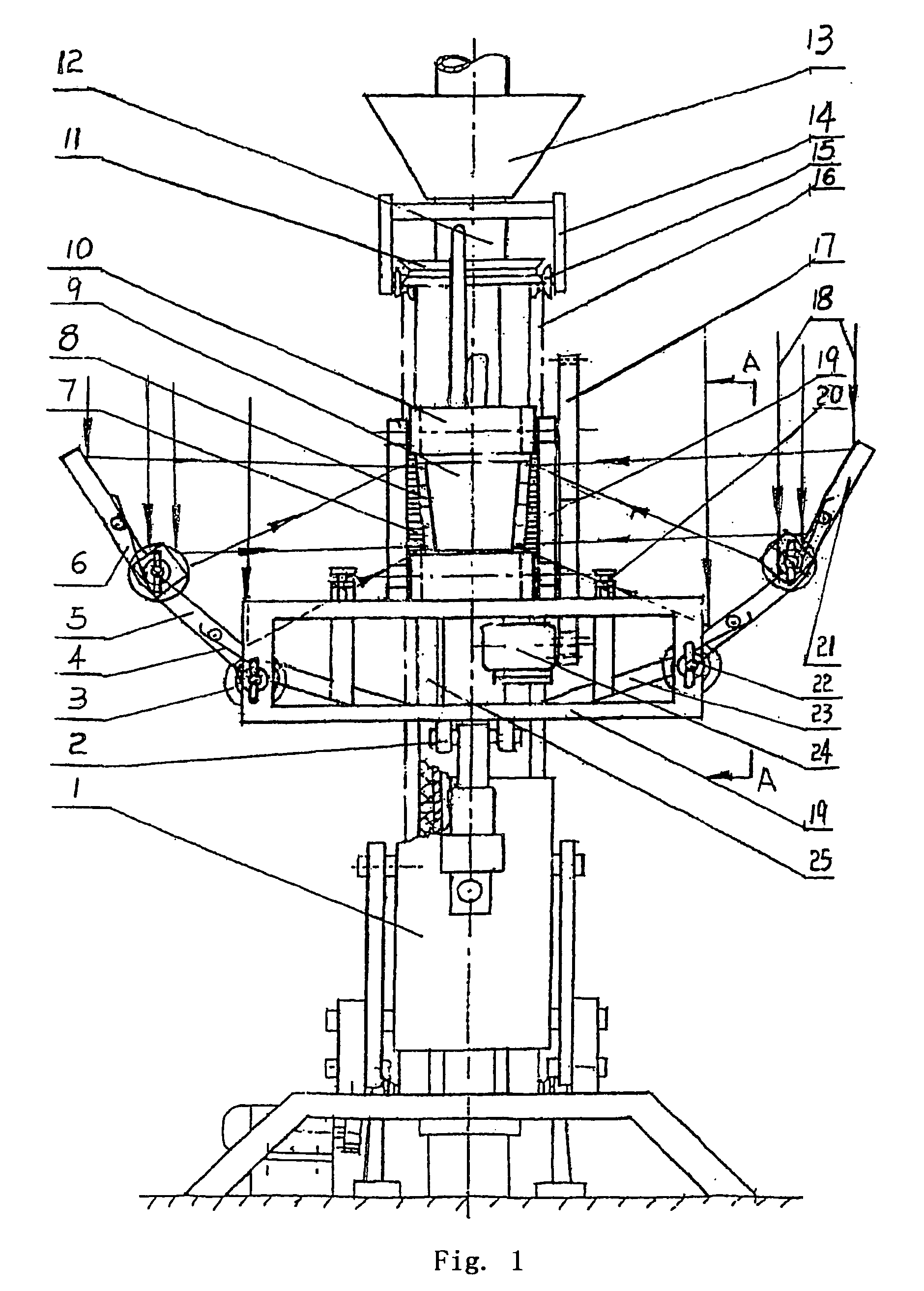
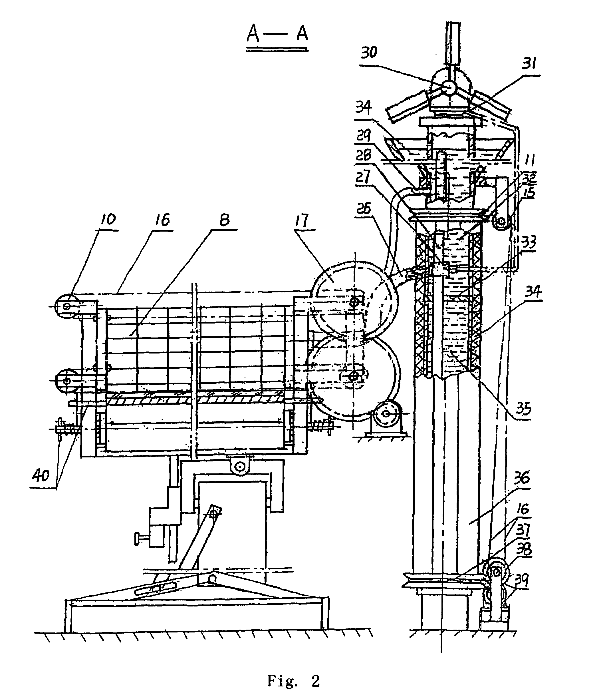
[0060]In FIGS. 1 and 2, reference number “1” is representative of the automatic sun-tracking machine; reference number “2” is the horizontal automatic tracking part of the sun-tracking machine; reference number “3” is the hydraulic anti-shake component; reference number “4” is the spring; reference number “5” is main sunlight collecting mirror which consists of flat reflective mirror and is connected to the collecting carrier 19 with a hinge shaft 22; reference number “6” is a west sub-collecting mirror hinged to the main sunlight collecting mirror 5; reference number “7” is a dust cleaning component for cleaning the dust, guano, leaves etc on the PV panel 8; reference number “9” is representative of the upright-plate PV power generating tube simply called “generating tube”, its two ends are fixed to the collecting carrier and the PV cells panel (as the cells panel is not vertical to the sunlight, so called “upright plate generator”) in any side of the generating tube is illuminated...


PUM


Abstract

An upright-plate type sunlight generator comprises up-right-plate type photovoltaic generating tubes capable of automatically cleaning dust, collecting mirrors with the automatic storm-sheltering mechanisms and a collecting carrier, a cooling and radiating system, and an automatic sun-tracking machine and its object carrier. The collecting mirrors are the folding mirrors made up of plane mirrors, and are connected to the photovoltaic generating tubes provided in the focal strip of the group of collecting mirrors during the operation on the support of the collecting carrier. The collecting carrier is immovably connected to the object carrier of the automatic sun-tracking machine, and the object carrier is connected to the automatic sun-tracking machine. The cooling and radiating system includes a liquid-cooling cavity that is the internal cavity of the photovoltaic generating tube, flexible connecting pipes and a liquid storing and cooling member.

Description

FIELD OF THE INVENTION[0001]The present invention relates to a solar photovoltaic (PV) power generation with high efficiency and low cost.BACKGROUND OF THE INVENTION[0002]In order to decrease the cost of the solar PV power generation and improve the efficiency of the photoelectric conversion, PV factories and the research institutes have spent a lot of time on improving the manufactory process and techniques, and found some more effective materials. However, the cost in the PV industry is relatively high, and the solar PV power generation still limits the commercial application though some achievements have been got.[0003]As there is a massive waste in the use of solar PV cells, we find the great potential to the solar PV industry.[0004]Firstly, most of solar PV power generating systems are in fixed state and work only 4 hours at peak even in a good whether condition, which is a waste to the solar PV power generation.[0005]Secondly, in order to decrease the waste as described above,...

Claims


Application Information

Patent Timeline
Patent Type & Authority Applications(United States)
IPC IPC(8): F24J2/46
CPCF03G6/06F24J2/16F24J2/38F24J2/405F24J2/461H01L31/054F24J2002/5486H01L31/052Y02E10/46Y02E10/47Y02E10/52F24J2/5417H01L31/0521H02S20/32H02S40/10H02S10/12F24S50/20F24S2030/16F24S30/45F24S40/20F24S50/60F24S23/77
Inventor WANAG, CUNYI
Owner WANG CUNYI
Learn More