Appliance selector switch programmed by console cutout

a selector switch and console technology, applied in the field of selector switches, can solve problems such as increasing the cost of machine manufactur

Inactive Publication Date: 2005-08-04
ILLINOIS TOOL WORKS INC
View PDF11 Cites 14 Cited by
  • Summary
  • Abstract
  • Description
  • Claims
  • Application Information

AI Technical Summary

Benefits of technology

[0007] The present invention provides a rotary selector switch whose rotational range is programmable, not by internal stops, but by a cutout in the console of the appliance to which the switch is mounted. The c...

Problems solved by technology

Designing, manufacturing and stocking three different switch...

Method used


Image

  • Appliance selector switch programmed by console cutout
  • Appliance selector switch programmed by console cutout
  • Appliance selector switch programmed by console cutout

Examples


first embodiment

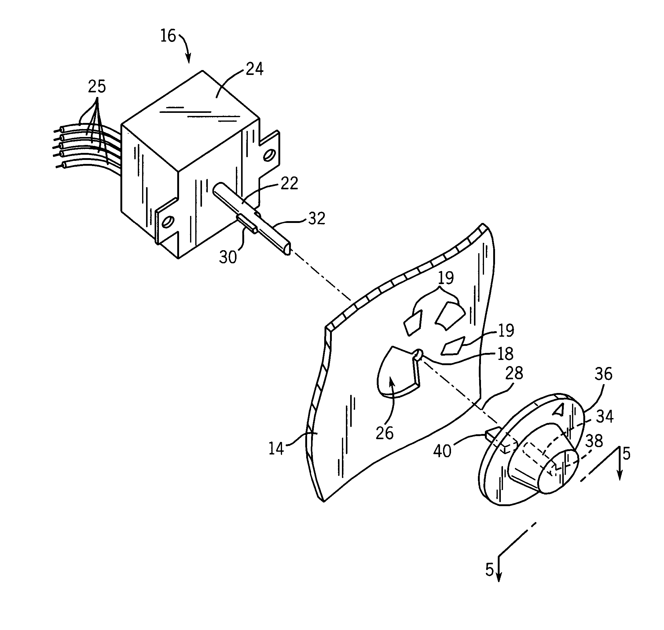
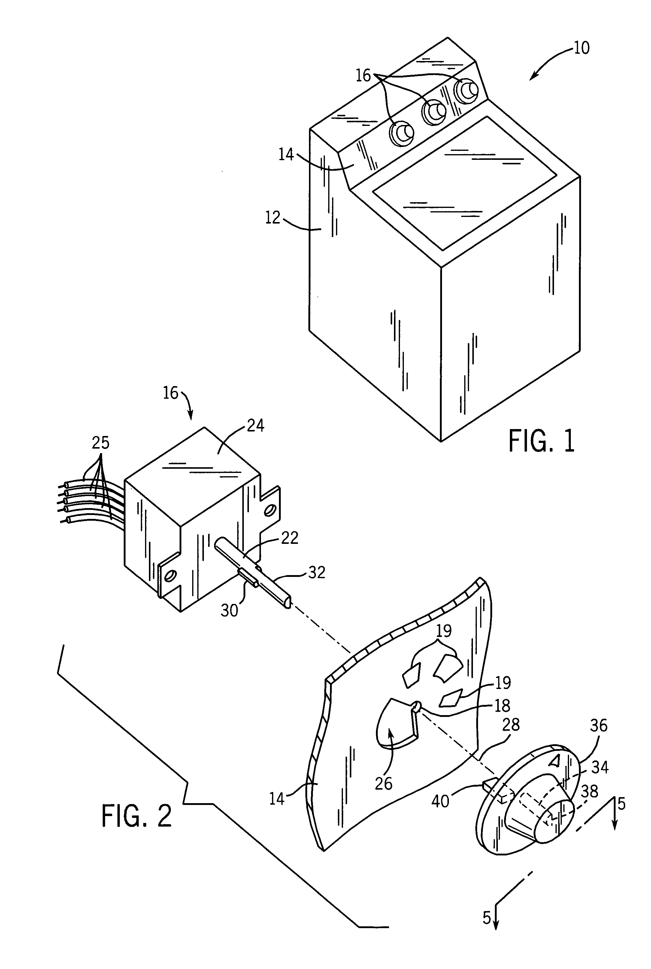
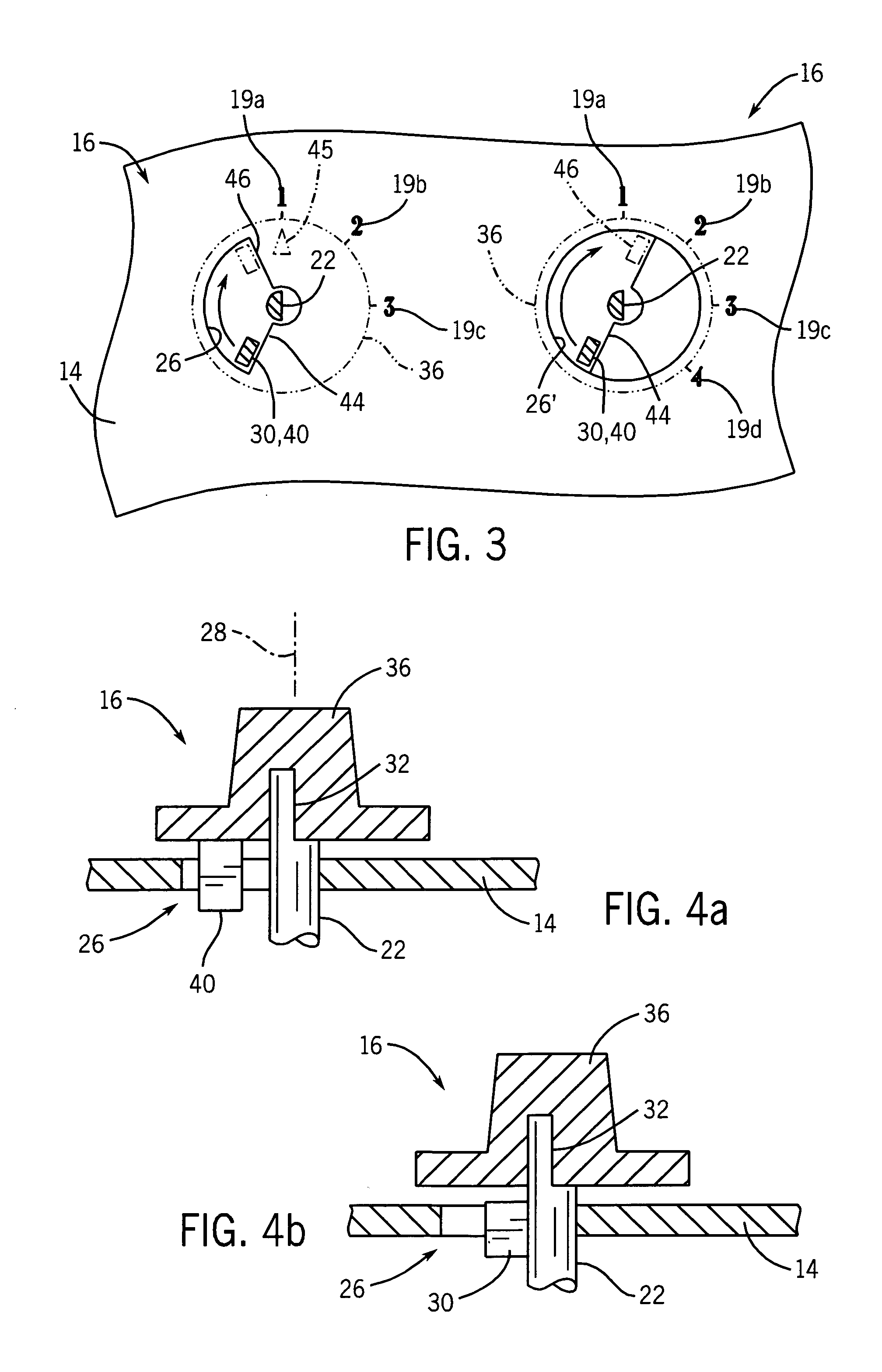
[0027] In a first embodiment shown in FIGS. 2 and 4b, the shaft 22 may have a radially extending tooth 30 that may fit into the rotational limit cutout 26 when a switchbox 24 of the selector control 16 is mounted at the rear of the console 14 with the shaft 22 projecting through the aperture 18. As the shaft 22 is turned, the tooth 30 swings through the rotational limit cutout 26, stopping at a clockwise and counterclockwise position by interference between the tooth 30 and the radial walls of the rotational limit cutout 26.

[0028] The shaft 22 may have a flat 32 fitting within a corresponding hole 34 with a flat 38 in a knob 36 and serving to rotationally key the shaft 22 with respect to knob 36. The knob 36 may be press fit or otherwise attached to the shaft 22 to rotate therewith.

second embodiment

[0029] In a second embodiment shown in FIGS. 2 and 4a, the knob 36 may have an axial tooth 40 extending rearwardly from the rear side of the knob 36 into the rotational limit cutout 26 to operate in a manner similar to that of tooth 30.

[0030] Referring to FIGS. 2 and 3, the front face of the console 14 may have indicia 19 corresponding to particular operating modes of the appliance 10 that may be selected by the selector control 16 as it moves through a range of control positions. The switchbox 24 typically provides internal electrical contacts controlled by a rotational position of the shaft 22 to different control positions, the contacts providing electrical signals over wires 25 indicating the control positions according to methods well known in the art. The switchbox 24 may provide detent positions at each control position. The present invention contemplates the use of a switchbox 24 having a standard number of control positions greater or equal to the largest number of control ...


PUM


Abstract

A console switch assembly for appliances provides a rotatable electronic switch having a rotational range constrained by a cutout in the control panel to which the switch is mounted. The cutout most simply may be a sector of a circle having a different angular range which constrains a projecting tooth on the shaft of the switch or knob attached to the shaft of the switch.

Description

CROSS-REFERENCE TO RELATED APPLICATIONS [0001] This application is based on provisional application 60 / 540,471 filed Jan. 30, 2004 and entitled Method for Setting Switch Travel During Final Assembly into Product and claims the benefit thereof.STATEMENT REGARDING FEDERALLY SPONSORED RESEARCH OR DEVELOPMENT BACKGROUND OF THE INVENTION [0002] The present invention relates to selector switches for appliances such as washing machines, and in particular to a selector switch having the number of selector positions determined by a cutout in the panel to which it is mounted. [0003] Appliance manufacturers often want to offer different models of a given appliance for different market segments. For example, a manufacturer may offer a high-end washing machine with eight different water level settings, a mid-range washing machine with six different water level settings, and a low-end washing machine with three different water level settings. [0004] Each water level setting may be selected by mov...

Claims


Application Information

Patent Timeline
IPC IPC(8): H01H19/03H01H19/14
CPCH01H19/03H01H2300/042H01H19/14
Inventor HOWIE, DAVID MALCOLM
Owner ILLINOIS TOOL WORKS INC
Why Eureka
Try Eureka