Vehicular occupant protection system

a technology for occupant protection and vehicles, applied in pedestrian/occupant safety arrangements, testing/monitoring control systems, instruments, etc., can solve problems such as misoperation of air bag sensors and inability to accurately diagnose abnormality of air bag sensors

Inactive Publication Date: 2005-08-04
DENSO CORP
View PDF7 Cites 18 Cited by
  • Summary
  • Abstract
  • Description
  • Claims
  • Application Information

AI Technical Summary

Benefits of technology

[0015] In a conventional system, after an abnormality diagnosis of a first sub-system is terminated, an abnormality diagnosis of a second sub-system is started. However, in the above structure, while a first sub-system is executing the abnormality diagnosis since an abnormality-diagnosis start command is outputted to the first sub-system, an abnormality-diagnosis s

Problems solved by technology

However, when an input terminal for the abnormality-diagnosis signals experiences electrical noises, the air bag sensor somet

Method used


Image

  • Vehicular occupant protection system
  • Vehicular occupant protection system
  • Vehicular occupant protection system

Examples


first embodiment

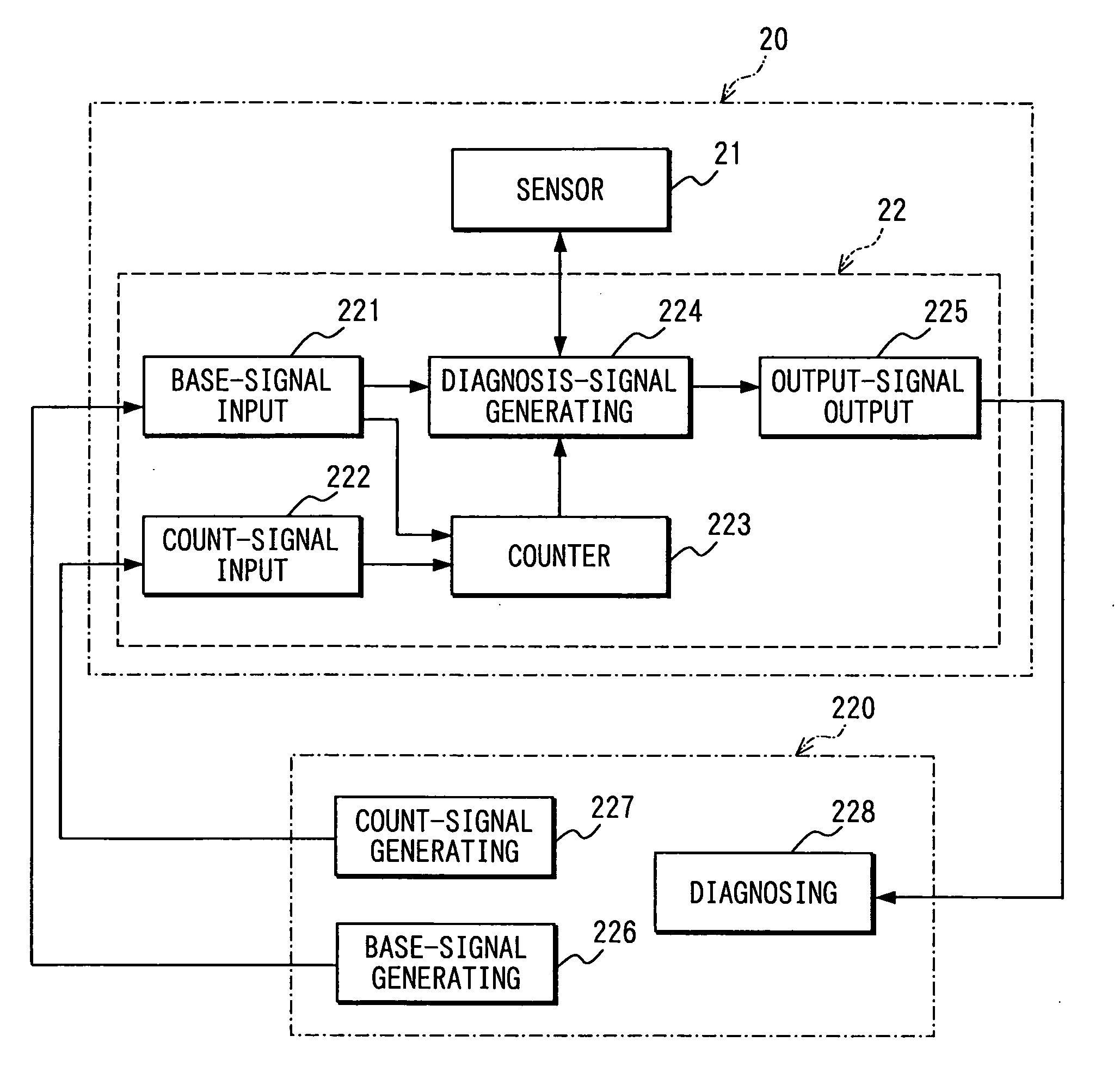
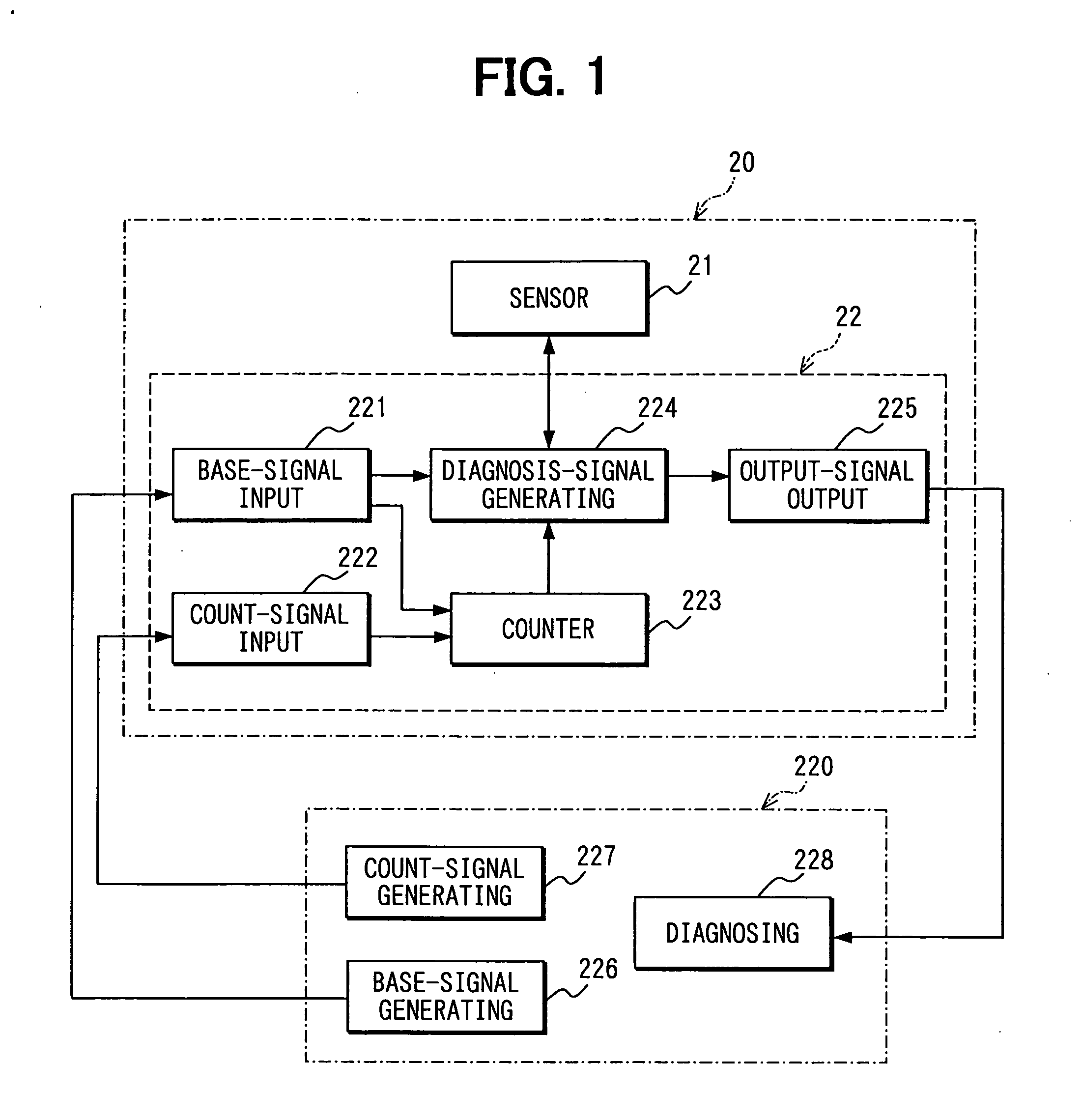
[0023] As shown in FIG. 1, a vehicular occupant protection system according to a first embodiment of the present invention includes an air bag ECU 220 and an acceleration sensor unit 20. The air bag sensor ECU 220 executes an ignition control of an air bag module base on an output signal of an acceleration sensor 21 while performing an abnormality diagnosis (or failure diagnosis) for the acceleration sensor 21. The air bag ECU 220 is disposed in an approximately central portion in a vehicle. Here, in this embodiment, only an abnormality diagnosis for an acceleration sensor 21 will be explained, while an ignition control for an air bag module will be eliminated from explanation. Further, in this embodiment, only an initial diagnosis, i.e., a primary check will be explained from within an abnormality diagnosis for an acceleration sensor 21.

[0024] The air bag ECU 220 includes a base-signal generating unit 226, a count-signal generating unit 227 as a condition-signal generating unit, a...

second embodiment

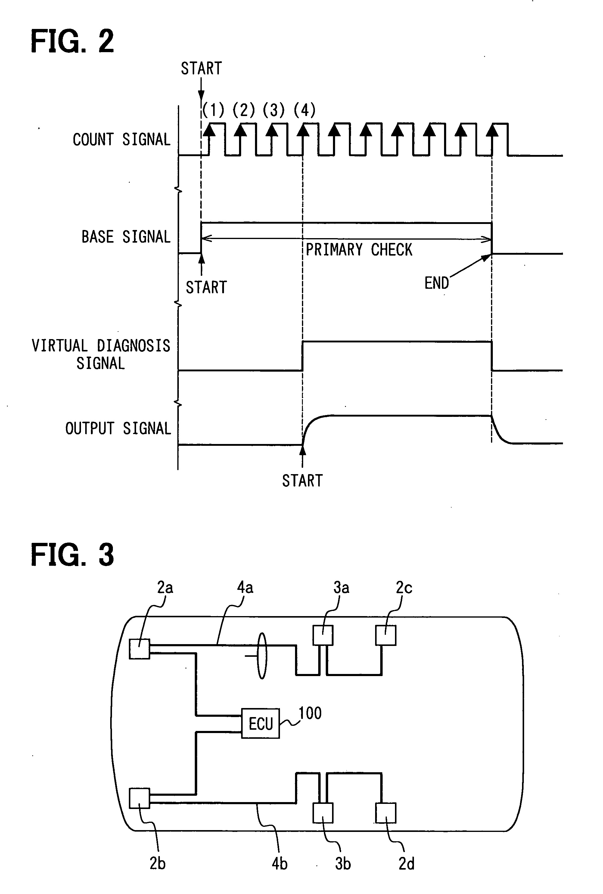
[0039] A structure of a vehicular occupant protection system according to a second embodiment will be explained with reference to FIGS. 3 to 5. As shown in FIG. 3, the vehicular occupant protection system includes an air bag ECU 100 as a main control unit; acceleration sensor sub-systems 2a to 2d; load sensor sub-systems 3a, 3b; and bus lines 4a, 4b.

[0040] The air bag ECU 100 executes abnormality determining, vehicle collision determining, or air bag ignition for the acceleration sensor sub-systems 2a to 2d and the load sensor sub-systems 3a, 3b. In the abnormality determining, abnormality-diagnosis start commands are outputted to the respective sub-systems 2a to 2d, 3a, 3b, while whether any sub-system is in an abnormal state is determined by using abnormality-diagnosis results and corresponding ID codes.

[0041] The abnormality-diagnosis start command is for causing each of the sub-systems 2a to 2d, 3a, 3b to start an abnormality diagnosis. The vehicle collision determining determ...


PUM


Abstract

A vehicular occupant protection system includes an air bag sensor; a base signal generating unit that generates a base signal for abnormality diagnosis for the air bag sensor; a diagnosis-signal generating unit that generates a diagnosis signal for the air bag sensor base on the base signal; an abnormality diagnosing unit that executes the abnormality diagnosis by using output signal that the air bag sensor outputs based on the diagnosis signal; and a condition-signal generating unit that generates a condition for a start of generating of the diagnosis signal. Here, the diagnosis-signal generating unit generates the diagnosis signal based on the base signal when the condition signal satisfies a given condition.

Description

CROSS REFERENCE TO RELATED APPLICATIONS [0001] This application is based on and incorporates herein by reference Japanese Patent Applications No. 2004-21999 filed on Jan. 29, 2004 and No. 2004-21992 filed on Jan. 29, 2004. FIELD OF THE INVENTION [0002] The present invention relates to a vehicular occupant protection system that is capable of restricting mis-operation in its abnormality diagnosis for an air bag sensor. BACKGROUND OF THE INVENTION [0003] Patent document 1 describes an abnormality diagnosis such as a primary check in an air bag sensor of a vehicular occupant protection system. Here, pulse signals (diagnosis signals, abnormality-diagnosis signals) with given intervals are inputted to the air bag sensor, so that an abnormality diagnosis is executed based on output signals from the air bag sensor. However, when an input terminal for the abnormality-diagnosis signals experiences electrical noises, the air bag sensor sometimes involves mis-operation. That is, an abnormality...

Claims


Application Information

Patent Timeline
IPC IPC(8): B60R21/01G05B23/00
CPCB60R21/01B60R2021/01184B60R2021/0117B60R2021/01068
Inventor TANAKA, TATSUKIKUMAZAWA, HIDEHIKO
Owner DENSO CORP
Why Eureka
Try Eureka