Vacuum cup

a vacuum cup and vacuum technology, applied in the field of vacuum cups, can solve the problems of premature failure of vacuum cups and excessive wear of vacuum cups, and achieve the effects of prolonging the life cycle of vacuum cups, reducing the amount of force and stress, and reducing the wear of vacuum cups

Active Publication Date: 2005-08-04
DELAWARE CAPITAL FORMATION
View PDF35 Cites 33 Cited by
  • Summary
  • Abstract
  • Description
  • Claims
  • Application Information

AI Technical Summary

Benefits of technology

[0008] The present invention provides a vacuum cup for a material handling system that is configured to automatically at least partially relieve or release or vent the vacuum or partial vacuum between'the vacuum cup and an attached object as the vacuum cup is pulled from the object. Because the vacuum between the vacuum cup and the object is at least partially relieved when the vacuum cup is initially pulled, the vacuum cup may then be removed from the object with a reduced amount of force and stress on the vacuum cup and, thus, will reduce the wear on the vacuum cup and prolong the life cycle of the vacuum cup. The relief port may partially relieve the vacuum and the vacuum cup may be removed with reduced stress while the partial vacuum (such as from a vacuum source) is still applied to the vacuum cup or after the vacu} m source is deactivated or disconnected from the vacuum cup, without affecting the scope of the present invention.

Problems solved by technology

However, the pulling of the vacuum cup or cups from the object while the vacuum is applied between the vacuum cup and the object may cause excessive wear to the vacuum cups and, thus, may lead to premature failure of the vacuum cups over time.

Method used


Image

  • Vacuum cup
  • Vacuum cup
  • Vacuum cup

Examples


Embodiment Construction

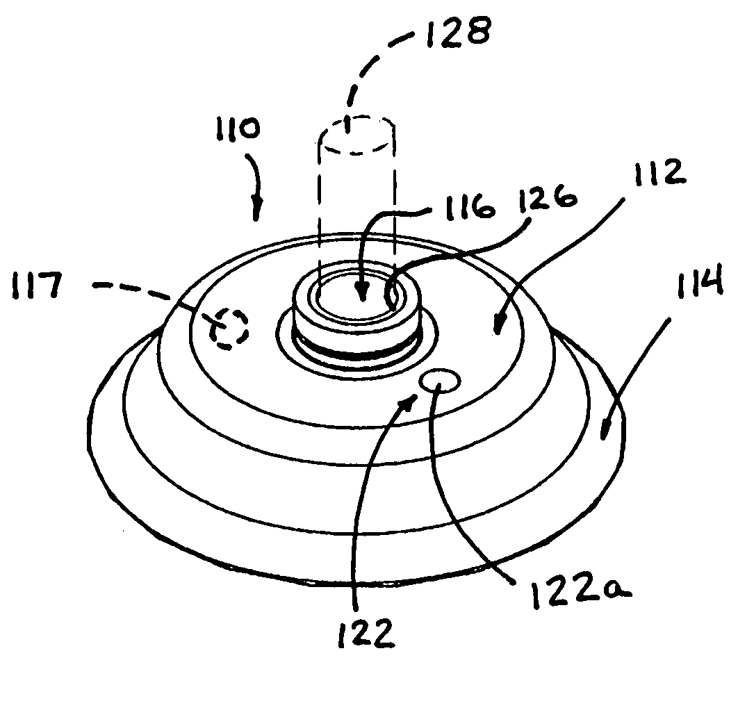
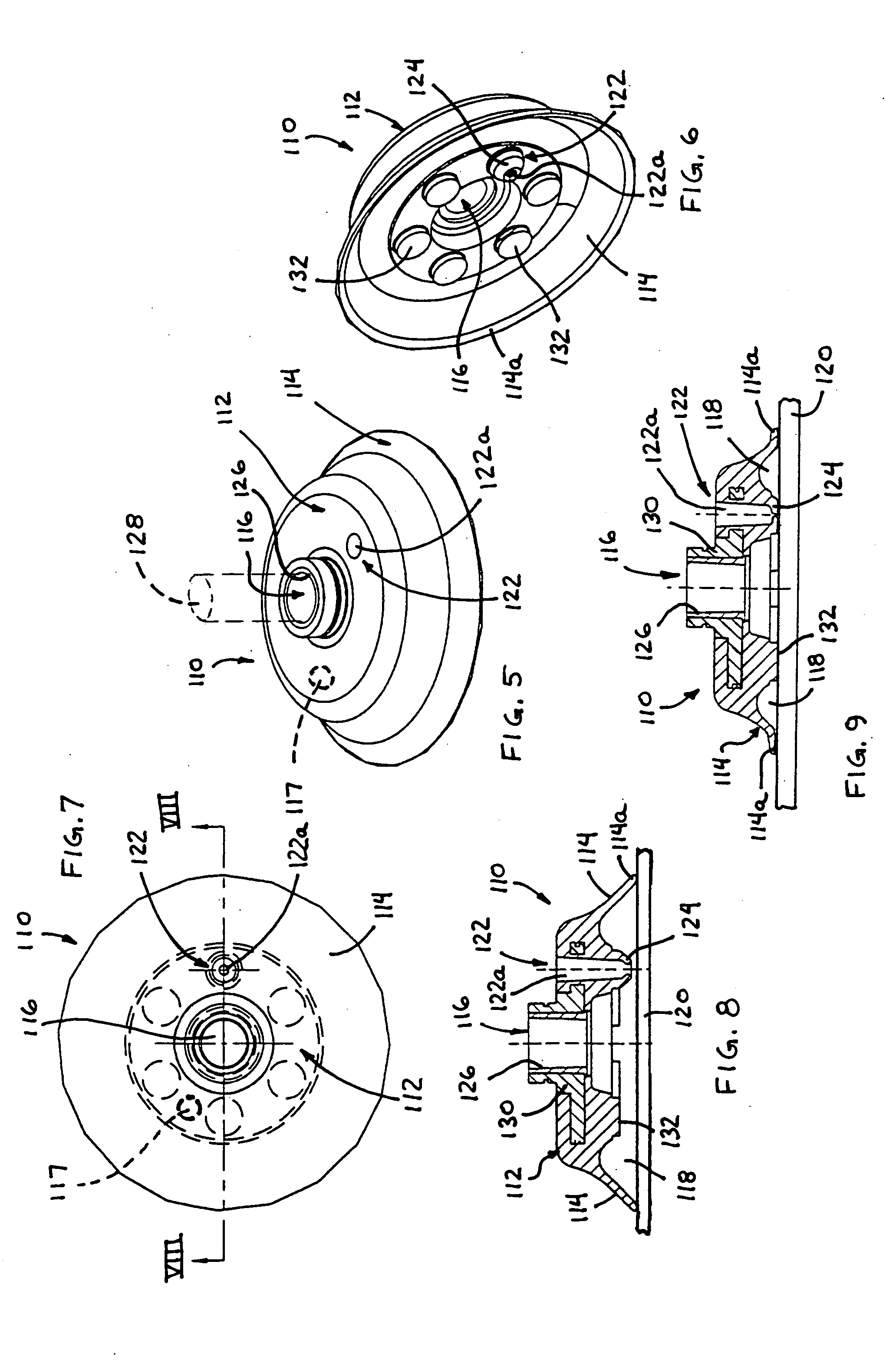
[0027] Referring now to the drawings and the illustrative embodiments depicted therein, a vacuum cup 110 for a material handling device or system includes a body portion 112 and a perimeter seal portion 114 (FIGS. 5-9). Vacuum cup 110 includes a vacuum port 116 for drawing air out of a cavity 118 defined by the body portion 112 and perimeter seal 114 and an object 120 (FIGS. 8 and 9) engaged with the perimeter seal 114. Vacuum cup 110 further includes a relief port 122, which defines a passageway 122a through body portion 112 and which includes an inner seal or sealing member or valve 124 that functions to open and close passageway 122a of relief port 122 when inner seal 124 is moved away from and into engagement with the object 120, respectively, as discussed below. Vacuum cup 110 may be connected to a vacuum source (not shown) which may be operable to draw air from cavity 118 through vacuum port 116 to at least partially evacuate the air from the cavity and create a partial or sub...


PUM


Abstract

A vacuum cup for a material handling system includes a body portion and a perimeter seal that functions to substantially seal against an object. The vacuum cup may transport the object when a partial vacuum is applied to the vacuum cup to retain the cup to the object. The vacuum cup includes a relief port and sealing member that function to at least partially relieve the vacuum from the vacuum cup to allow the vacuum cup to be detached from the object with a reduced force, even while the vacuum is applied. The sealing member may engage a surface of the object to close the relief port. When the vacuum cup is initially pulled or moved away from the object, the sealing member is at least partially separated from the object and allows the cavity to be vented to at least partially relieve the vacuum within the cavity.

Description

CROSS REFERENCE TO RELATED APPLICATION [0001] The present application claims the benefit of U.S. provisional application Ser. No. 60 / 541,636, filed Feb. 4, 2004, which is hereby incorporated herein by reference in its entirety.FIELD OF THE INVENTION [0002] The present invention relates generally to material handling systems and, more particularly, to material handling systems that handle objects via vacuum cups or suction cups engaged with the objects and substantially sealed thereto. BACKGROUND OF THE INVENTION [0003] It is known to provide material handling systems that include vacuum cups or the like that are adapted to be engaged with an object, such as a substantially flat object or panel or the like, and to lift and move the object to a desired location. Such vacuum cups or suction cups may be moved into engagement with the object, and a vacuum source may be actuated to create a vacuum between the object and the cup such that the object is retained to the cup as it is transpor...

Claims


Application Information

Patent Timeline
Patent Type & Authority Applications(United States)
IPC IPC(8): B25B11/00B25J15/06B65G47/91
CPCB25B11/005B65G47/91B25J15/0616B25B11/007
Inventor PERLMAN, MAURICEATTEE, KEITH S.
Owner DELAWARE CAPITAL FORMATION
Why Eureka
Try Eureka