Zoom lens system

a zoom lens and zoom technology, applied in the field of zoom lens systems, can solve the problems of difficult miniaturization of front lens diameter, difficult to obtain a high zoom ratio, and decrease of peripheral light quantity, so as to improve peripheral light quantity at the wide-angle end, and optical performance in the entire zoom range from the wide-angle end to the telephoto end is excellent

Inactive Publication Date: 2005-08-04
CANON KK
View PDF4 Cites 12 Cited by
  • Summary
  • Abstract
  • Description
  • Claims
  • Application Information

AI Technical Summary

Benefits of technology

[0020] An object of the present invention is to provide a zoom lens system in which the decrease of the peripheral light quantity at the wide-angle end is improved and its optical performance in the entire zoom range from the wide-angle end to the telephoto end is excellent.

Problems solved by technology

Moreover, in the zoom lens disclosed by Patent Document 4, it is difficult to obtain a high zoom ratio since the first lens unit is a single lens, and the refractive power of the first and second lenses are not so large.
Moreover, in the zoom lens disclosed by Patent Document 5, it is difficult to miniaturize the front lens diameter since the movement tracks of lens units for zooming are not necessarily the best.
Therefore, there is a problem that the decrease of the peripheral light quantity stands out.

Method used


Image

  • Zoom lens system
  • Zoom lens system
  • Zoom lens system

Examples


Embodiment Construction

[0037] Hereinafter, a zoom lens system and an image-taking apparatus using the same of preferred embodiments of the present invention will be concretely described with referent to the drawings.

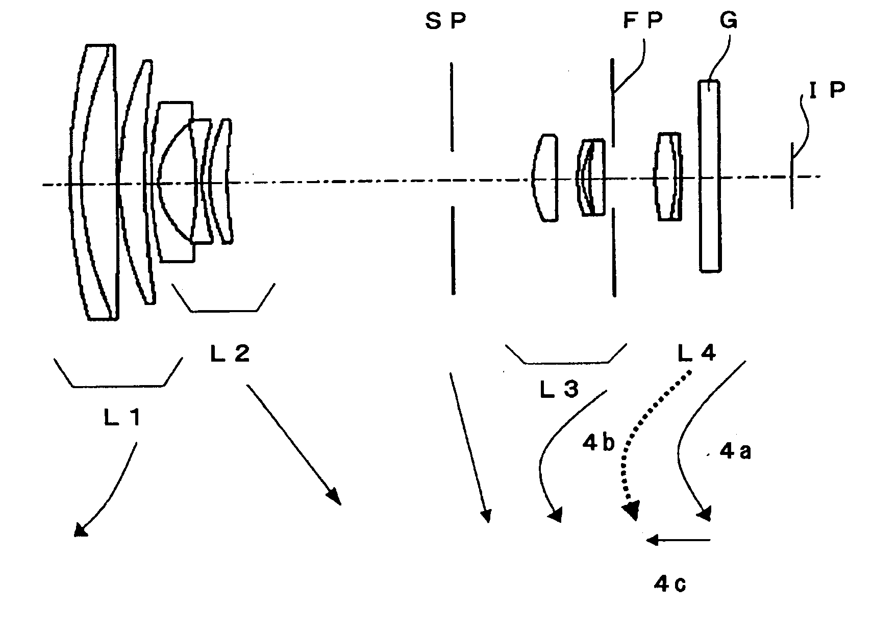
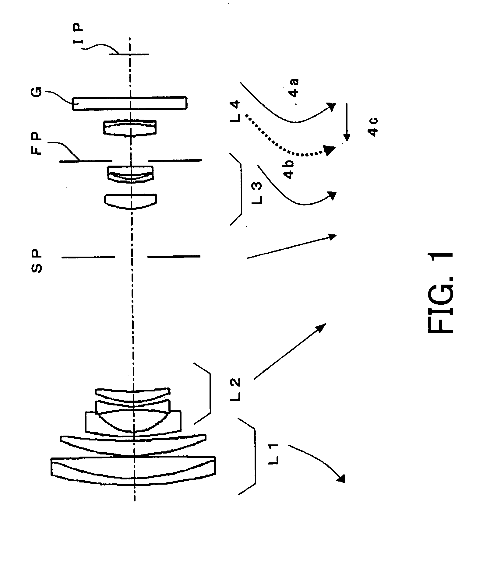
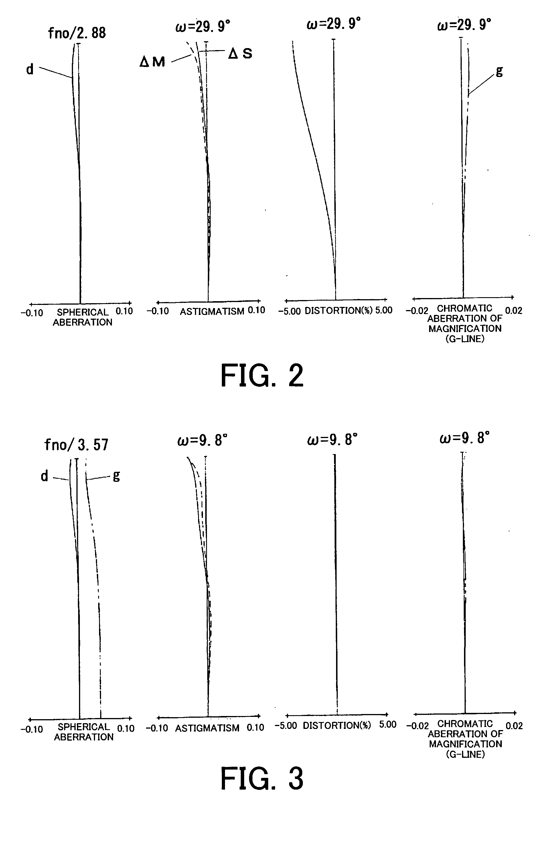
[0038]FIG. 1 is a section view of the zoom lens at the wide-angle end in Embodiment 1 of the present invention, and FIGS. 2 to 4 show aberration charts of the zoom lens in Embodiment 1 at the wide-angle end, at the middle focal length and at the telephoto end.

[0039] FIGS. 5 to 7 show aberration charts of the zoom lens in Embodiment 2 of the present invention at the wide-angle end, at the middle focal length and at the telephoto end. The section view of the zoom lens in Embodiment 2 is omitted because it is almost the same as Embodiment 1.

[0040]FIG. 8 is a section view of the zoom lens at the wide-angle end in Embodiment 3 of the present invention, and FIGS. 9 to 11 show aberration charts of the zoom lens in Embodiment 3 at the wide-angle end, at the middle focal length and at the telephoto ...


PUM


Abstract

A zoom lens system is disclosed, in which the decrease of the peripheral light quantity at the wide-angle end is improved. The zoom lens system comprises, in order from an object side to an image side, a first lens unit having a positive optical power, a second lens unit having a negative optical power, an aperture stop, a third lens unit having a positive optical power and a fourth lens unit having a positive optical power. The four lens units and the aperture stop are moved during zooming. When MS represents movement amount of the aperture stop during zooming from the wide-angle end to the telephoto end and M3 represents the maximum movement amount of the third lens unit in the optical axis direction during zooming from the wide-angle end to the telephoto end, −1.8<MS / M3<−0.5 is satisfied.

Description

BACKGROUND OF THE INVENTION [0001] 1. Field of the Invention [0002] The present invention relates to a zoom lens system suitable for, for instance, image-taking apparatuses such as video cameras, digital still cameras and silver halide cameras. [0003] 2. Description of the Related Art [0004] Recently, remarkable advancement of the miniaturization of zoom lenses for image-taking, which is associated with the miniaturization and weight reduction of home video cameras, etc., is seen, and especially, shortening the total length of the lens system, miniaturizing the front lens diameter and simplifying the lens composition are attempted. [0005] As one of means to achieve these purposes, a so-called rear focus type zoom lens is known, in which a lens unit other than the first lens unit on the object side is moved for focusing. [0006] Generally, in the rear focus type zoom lens, an effective diameter of the first lens unit is small as compared with a zoom lens in which the first lens unit i...

Claims


Application Information

Patent Timeline
Patent Type & Authority Applications(United States)
IPC IPC(8): G02B13/18G02B15/173G02B15/20
CPCG02B27/646G02B15/173G02B15/144113
Inventor HAMANO, HIROYUKI
Owner CANON KK
Why Eureka
Try Eureka