
Electronic lighting unit and photographic equipment with the electronic lighting unit

a technology of electronic lighting and electronic lighting, which is applied in the field of electronic lighting units and photographic equipment with electronic lighting units, can solve the problems of increasing the number of parts, increasing the power consumption according, and reducing the efficiency of optical communication, so as to reduce the effect of red eye effect or alleviation

Inactive Publication Date: 2005-08-04
FUJI PHOTO OPTICAL CO LTD
View PDF7 Cites 82 Cited by
  • Summary
  • Abstract
  • Description
  • Claims
  • Application Information

AI Technical Summary

Benefits of technology

[0010] It is another object of the present invention to provide a lighting unit comprising a plurality of light emitting elements that measures up reliable lighting efficiency and ensured power saving.
[0012] According to the configuration, since it is ensured that only light emitting elements selected to comply with an intended lighting pattern are excited, the lighting unit produces light efficiently for subjects and makes for power saving as well.
[0014] The lighting pattern directive means is preferred to direct the selective excitation mean to excite selectively the light emitting elements to produce flash light in predetermined different lighting patterns according to at least one of optical and electronic zoom ratios of the image pickup system. In this instance, the electronic zoom ratio as used herein shall mean and refer to a ratio (a trimming ratio or an extraction ratio) of a trimming or extraction image area relative to a given image area of the image pickup device. This configuration causes the lighting unit to produce flash light efficiently for subjects.
[0017] The lighting pattern directive means may further direct the selective excitation mean to excite selectively the light emitting elements to produce flash light in different lighting patterns for purposive pre-lighting for automatic focusing convenience, determination of emission intensity for flash photo shooting, or elimination or alleviation of a red-eye effect. The lighting pattern directive means is preferred to direct the selective excitation mean that the selected light emitting elements produce flash light at intensity for the purposive pre-lighting than for flash photo shootings. According to this configuration, the lighting unit produces flash light efficiently toward a restricted field effective only for the purposive pre-lighting.
[0018] The photographic equipment may further comprise optical communication means for making optical communication with external equipments. In this instance, the lighting pattern directive means directs the selective excitation mean to excite the light emitting elements to produce flash light in a specific lighting pattern for optical communication. This configuration causes the lighting unit to produce flash light efficiently for optical communication.

Problems solved by technology

However, this simultaneous excitation encounters another problem that electric power consumption increases according to the number of excited white LEDs.
In particular, in the case where the single piece of white LED is installed in cellular phones having an optical communication feature in addition to the image import feature, if the white LED elements can produce high intensity of light, the cellular phone will be disabled to make calls and / or data communication due to a potential drop of batteries resulting from image import.
That is, there are two somewhat conflicting requirements that govern reliable lighting by simultaneous excitation of the white LEDs and power saving in opposition to simultaneous excitation of the white LEDs.
The mechanisms for changing a direction of lighting which the conventional lighting devices are equipped with are hardly downsized due to an inevitable increase in the number of parts.

Method used


Image

  • Electronic lighting unit and photographic equipment with the electronic lighting unit
  • Electronic lighting unit and photographic equipment with the electronic lighting unit
  • Electronic lighting unit and photographic equipment with the electronic lighting unit

Examples


Embodiment Construction

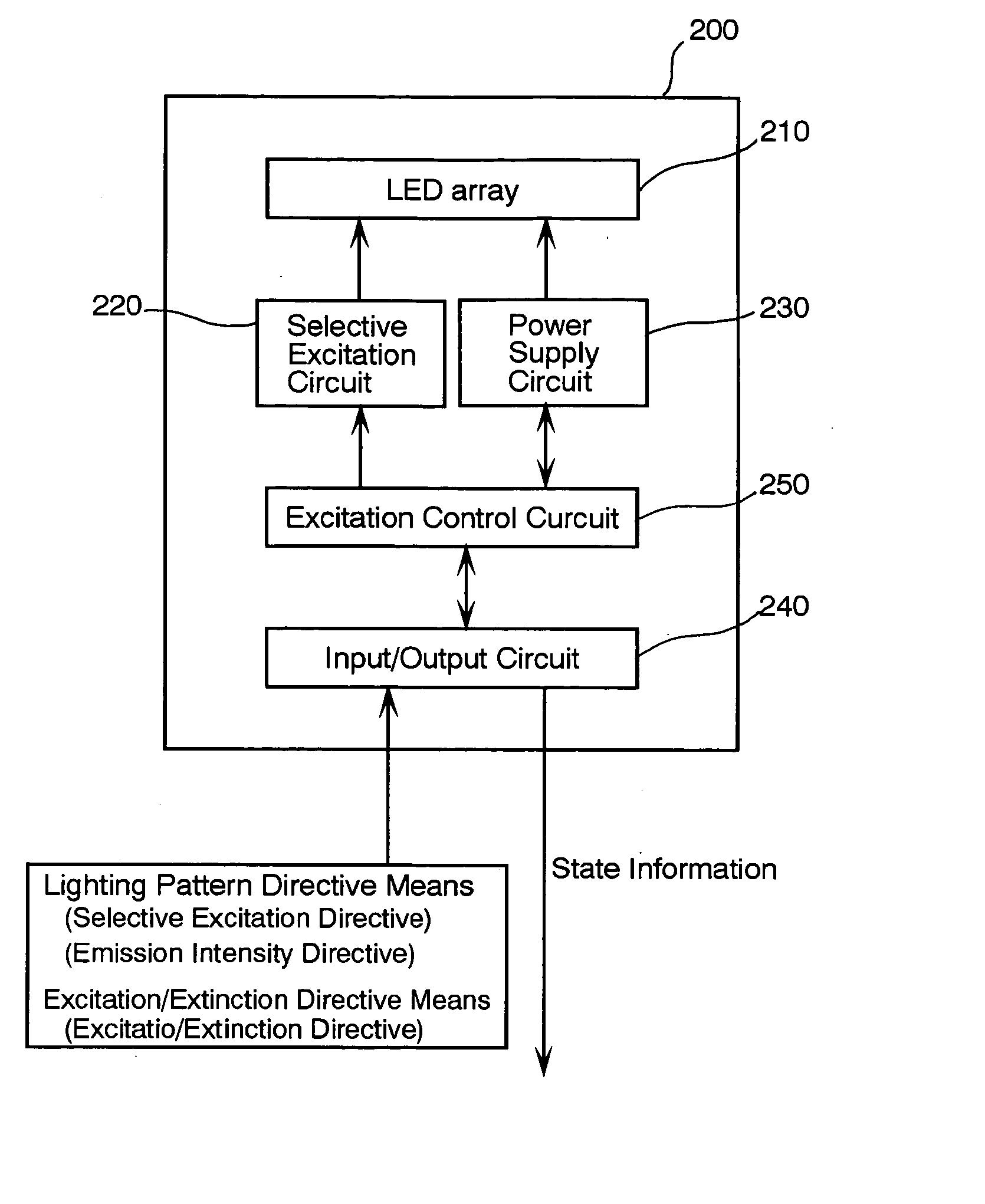
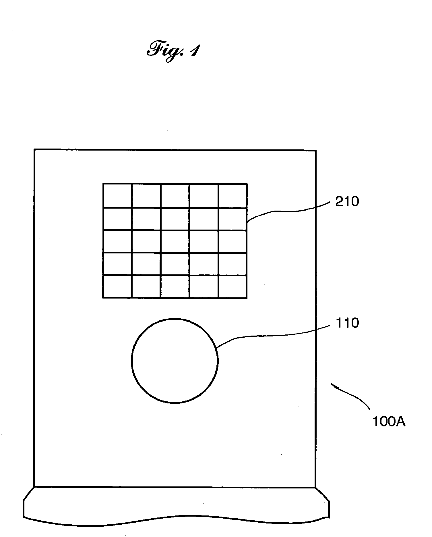
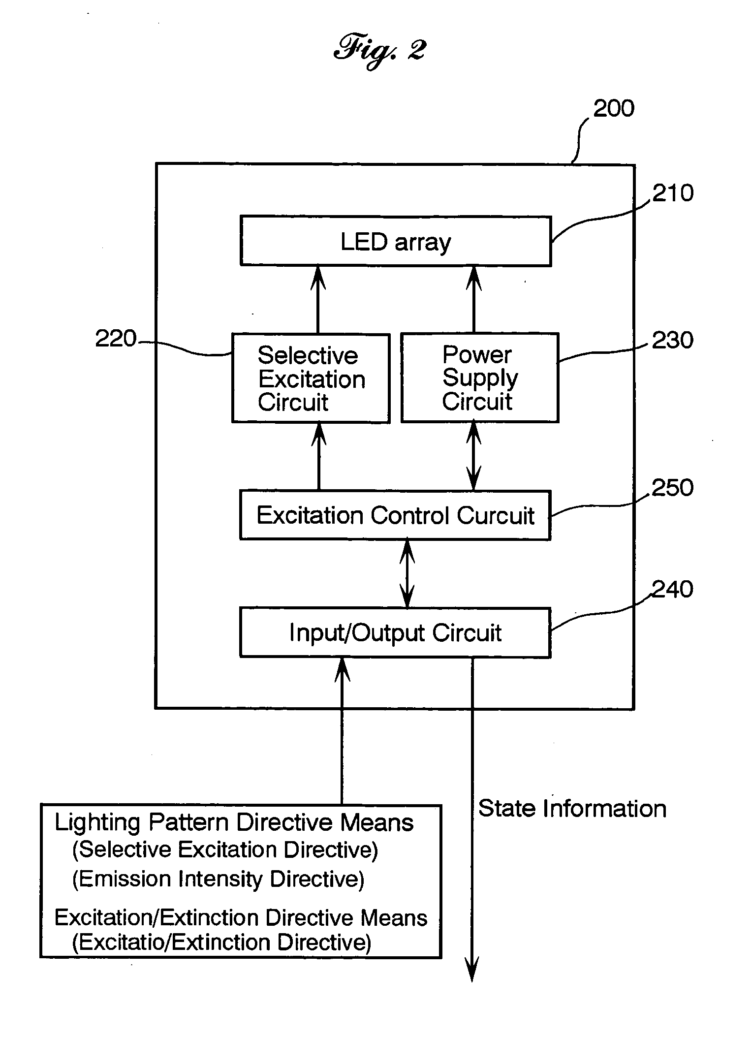
[0028] Referring to the accompanying drawings in detail, and in particular, to FIG. 1 schematically showing a photographic equipment, namely an image importable cellular phone 100A according to an embodiment of the present invention, the cellular phone 100A includes a taking lens 110 forming part of an image pickup system and an array of light emitting diodes (LEDs) (which is hereinafter referred to as an LED array) 210 forming part of a built-in lighting unit 200 (see FIG. 2) for producing subsidiary flash light which are installed into a top cover of the cellular phone 100A. that is aimed at subjects when opened. The LED array 210 comprises a number of white LED element arranged in a matrix pattern. These white LED elements have lighting axes different from one another so as to produce light toward different areas of a field of view of the taking lens 110, respectively. All of the incident light falling on the scene which includes available light, indoor illumination light, other ...


PUM


Abstract

A lighting unit for producing flash light toward subjects in a photographic scene comprises an matrix array of light emitting elements arranged so as to have individual lighting fields different from one another, a selective excitation circuit for exciting selectively the light emitting elements so as to produce flash light, different in intensity as appropriate, in predetermined lighting patterns and an excitation / extinction circuit 250 for exciting or extinguishing the light emitting elements. A photographic equipment equipped with the lighting unit has directive switches or buttons for directing the lighting unit to select lighting pattern according to focal lengths, zoom rations, operation modes including a communication mode, and / or demands of pre-lighting,

Description

BACKGROUND OF THE INVENTION [0001] 1. Field of the invention [0002] The present invention relates to a lighting unit, and, more particularly, a lighting unit comprising a plurality of light emitting elements, and a photographic equipment with the lighting unit built therein. [0003] 2. Description of Related Art [0004] Typically, one of photographic lighting or flash devices for subsidiarily lighting subjects that are most popular in the art is an electronic flash device. Such an electronic flash device is such that, when a high voltage stored in the capacitor is applied to the gas-discharge tube, the gas inside becomes ionized and then a rush of current flows through the gas the tube and it simultaneously emits a bright light by sudden discharge. [0005] Meanwhile, cellular phones with an images import feature that have recently been in widespread use are generally provided with lighting devices for lighting a subject to be imported. In general, such a lighting device built in the ce...

Claims


Application Information

Patent Timeline
Patent Type & Authority Applications(United States)
IPC IPC(8): G03B7/16E05B17/10G03B15/02G03B15/03G03B15/05H04N23/75
CPCH04N5/2354G03B15/05G03B2215/05H04N23/74
Inventor YOSHIDA
Owner FUJI PHOTO OPTICAL CO LTD
Learn More