Device providing coordinated emission of light and volatile active

a technology of volatile active and device, which is applied in the direction of semiconductor devices for light sources, lighting and heating apparatus, instruments, etc., can solve the problems of dripping wax damage to furniture and skin, few things are quite as versatile at setting the ambience in an area as scented candles, and scented candles are not without drawbacks. achieve the effect of reliable and effective volatile active delivery system

Inactive Publication Date: 2005-08-04
HELF THOMAS A +2
View PDF96 Cites 111 Cited by
  • Summary
  • Abstract
  • Description
  • Claims
  • Application Information

AI Technical Summary

Benefits of technology

[0008] Our invention provides a device that emits both light and scent (or other active ingredient) similar to a scented candle. More particularly, our invention

Problems solved by technology

Because of their wide array of shapes and sizes, as well as the seemingly limitless number of available scents, few things are quite as versatile at setting the ambience in an area as scented candles.
Scented candles are not without drawbacks, however.
For example, dripping wax can damage furniture and the skin and, in the extreme, an open fla

Method used


Image

  • Device providing coordinated emission of light and volatile active
  • Device providing coordinated emission of light and volatile active
  • Device providing coordinated emission of light and volatile active

Examples


first embodiment

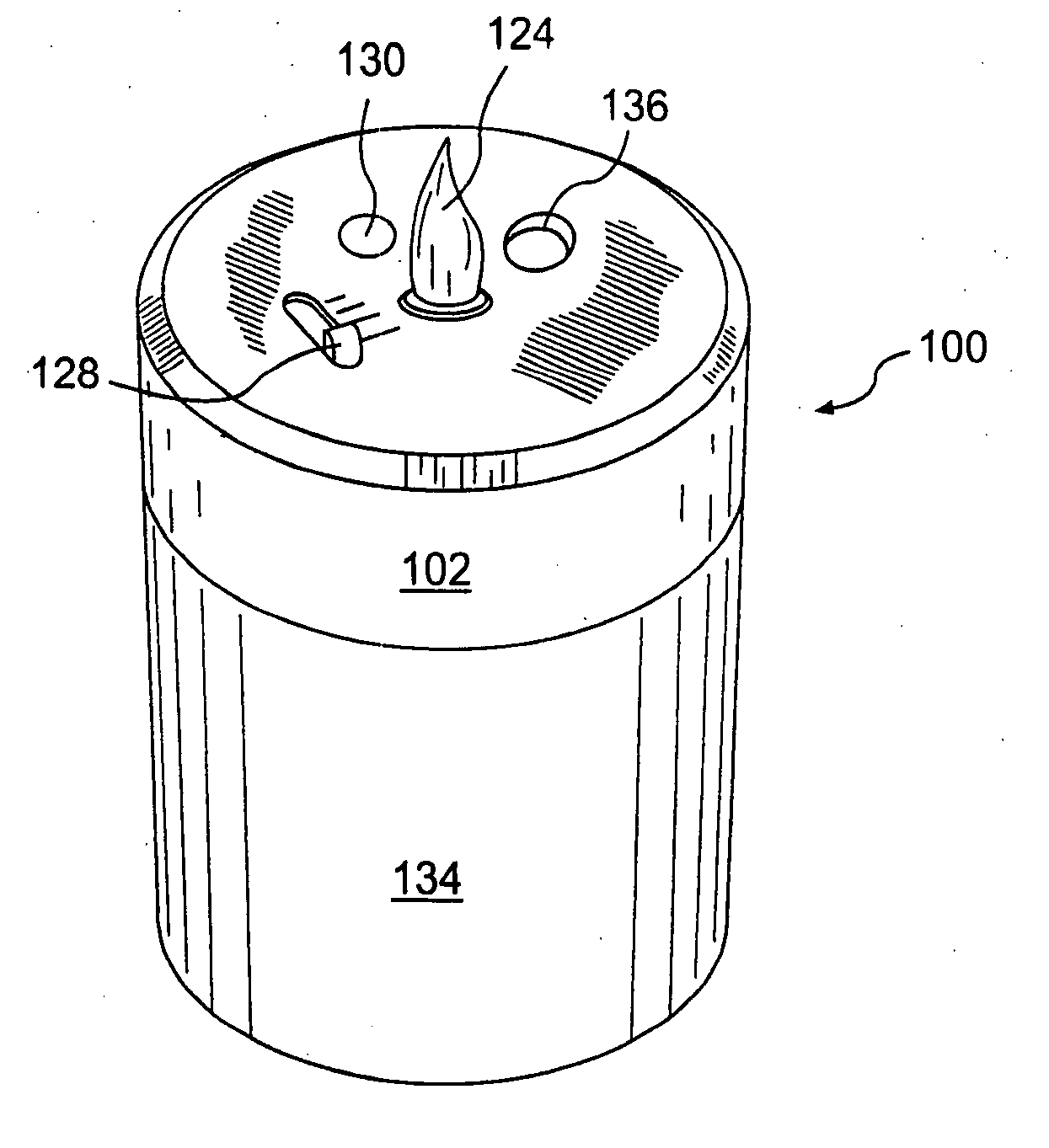
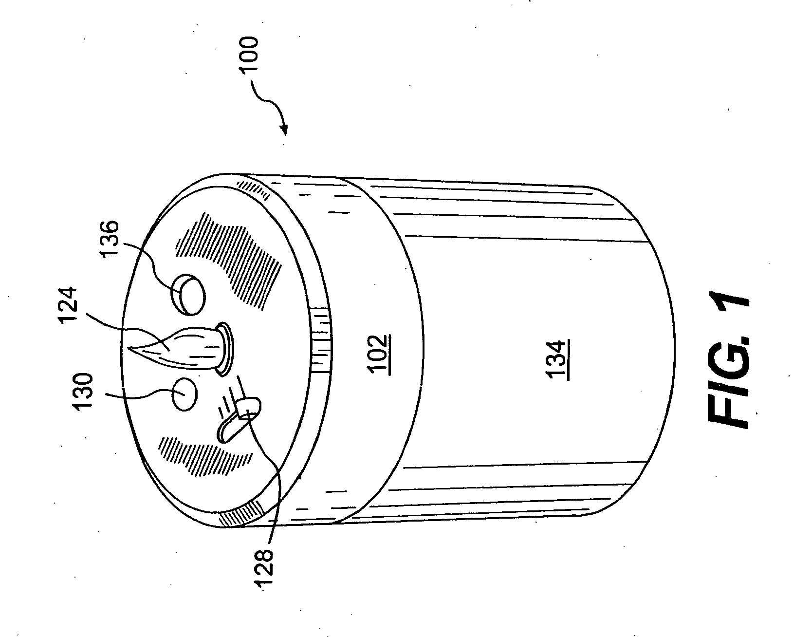
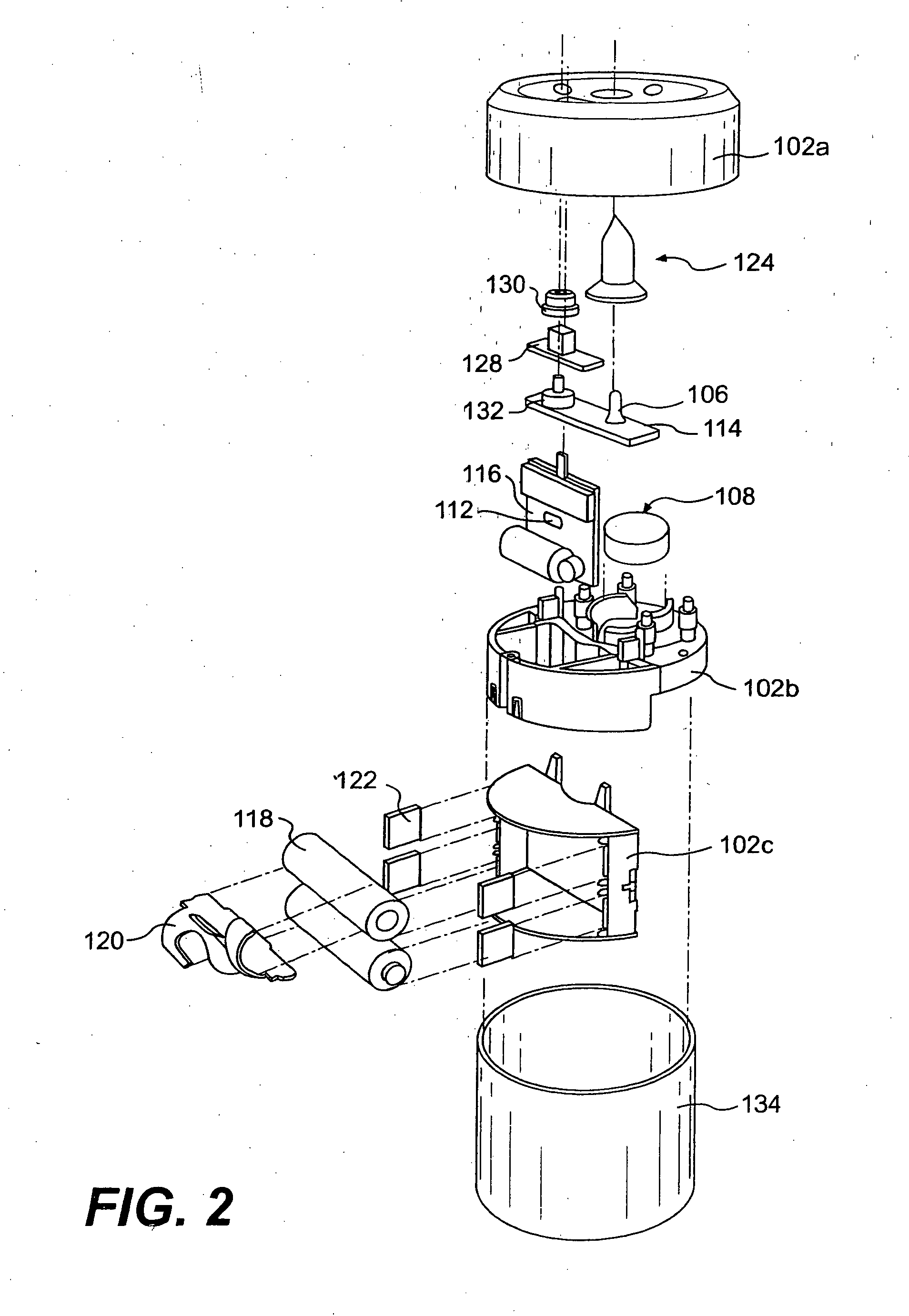
[0053] The first embodiment is depicted in FIGS. 1-5 and will be described with reference to those figures. As seen best in FIGS. 2 and 3, a chassis 102 is provided that includes a chassis cover 102a, a chassis upper portion 102b, and a chassis lower portion 102c. Disposed on the chassis 102 are two batteries 118, a wick-based atomizer assembly 108, a single LED 106, and two printed circuit boards 114, 116. Each of two microcontrollers 110, 112 are disposed on the circuit boards 114, 116. (While in this embodiment two microcontrollers 110, 112 (one for each of the LED 106 and the atomizer assembly 108) and two circuit boards 114, 116 (one for each of the LED 106 and the atomizer assembly 108), a single microcontroller and / or a single circuit board may be used to control both the LED 106 and the atomizer 108.) As shown, the chassis cover 102a and the chassis upper portion 102b are joinable to form a cavity therebetween, and the chassis lower portion 102c depends downwardly from a bot...

second embodiment

[0068] According to this second embodiment, a light and substance emitting device 200 is provided. Preferably, as mentioned above, the housing (i.e., the combined chassis 202 and base 234) of the device 200 is configured and sized to resemble a conventional pillar candle. As should be understood, since the LED 206 emitting the flickering light is disposed within the housing, much of the light will be transmitted through the sidewall of the base 234. Accordingly, at least a portion of the base 234 should be light transmissive. In addition, at least a portion of the chassis 202 may also be light transmissive. To these ends, all or a portion of the chassis 202 and / or the base 234 may be formed of one or more of glass, plastic, wax, and the like.

[0069] Variations of this second embodiment are also contemplated. For example, while the holder 234 is generally cylindrical, such is not required. Rectangular, square, and a myriad of other shapes and sizes are contemplated. In addition, while...

third embodiment

[0070] our invention will now be described with reference to FIGS. 8A-8C, 9, and 10. In this embodiment a preferred light and substance emitting device 300 of our invention includes a chassis 302 comprising a chassis cover 302a and a chassis base 302b which together form a cavity that encases each of two LEDs 306a, 306b, a fragrance emitter 308, two batteries 318, and a printed circuit board with microcontroller 310. The LEDs 306a, 306b are connected either directly or indirectly to both of the batteries 318 and the microcontroller 310. While the alignment of the fragrance emitter 308, the batteries 318, and the microcontroller 310 within the chassis 302 is not critical, each of these components is preferably located below a top surface of the chassis cover 302a. Also, the LEDs 306a, 306b are preferably located substantially centrally with respect to a top surface of the device, and above the fragrance emitter 308, the batteries 318, and the microcontroller 310, i.e., on a side of t...


PUM


Abstract

A light and substance emitting device (100) includes a light source (106), an emitter (108) a power source (118), control circuitry (110,112), and a support structure (102, 104, 134). The light source (106) emits a flickering light that emulates a flame of a candle. The emitter (108) emits a volatile active. The power source (118) supplies power to the light source (106) and to the emitter (108). The control circuitry (110,112) controls at least one of (i) the light source (106) to flicker and (ii) the emitter (108) to emit the volatile active. The support structure (102, 104, 134) supports the light source (106), the emitter (108), the power source (118) and the control circuitry (110, 112).

Description

RELATED APPLICATION [0001] This application claims the benefit of U.S. Provisional Application No. 60 / 541,067, filed Feb. 3, 2004.BACKGROUND OF THE INVENTION [0002] 1. Field of the Invention [0003] Our invention relates to the integrated presentation of ambient conditions. More specifically, our invention relates to the controlled and coordinated emission of light and volatile active, e.g., a fragrance, into a given area, such as a room, from a single device. [0004] 2. Description of the Related Art [0005] Because of their wide array of shapes and sizes, as well as the seemingly limitless number of available scents, few things are quite as versatile at setting the ambience in an area as scented candles. Scented candles are not without drawbacks, however. For example, dripping wax can damage furniture and the skin and, in the extreme, an open flame can lead to a structure fire. [0006] To account for the common problems associated with candles, electronic lighting devices that have a ...

Claims


Application Information

Patent Timeline
IPC IPC(8): A01M1/02A01M1/04A61L9/03A61L9/12A61L9/14F21V8/00G03G21/16
CPCA01M1/02A01M1/04A61L9/037A61L9/122A61L9/127F21S10/043A61L2209/12F21S6/001G02B6/0051G02B6/0068F21Y2101/02A61L9/14F21Y2115/10A61L9/12C11C5/00
Inventor HELF, THOMAS A.PORCHIA, JOSEWOLF, JEFFREY J.
Owner HELF THOMAS A
Why Eureka
Try Eureka