Automatic conveyor slot closure

a conveyor and slot technology, applied in the field of conveyors, can solve the problems of physical limitation of the shaft movement of the shaft toward or away from the end of the downstream conveyor, and achieve the effect of limiting the gap width

Inactive Publication Date: 2005-08-11
INT PAPER CO
View PDF9 Cites 29 Cited by
  • Summary
  • Abstract
  • Description
  • Claims
  • Application Information

AI Technical Summary

Benefits of technology

[0012] Recalling that the shaft, hence the shield, is mounted for hinged movement, spring or like means is provided to bias the shaft to an initial position spaced apart by a selected distance from the end of the downstream conveyor to develop an initial opening between the end of the downstream conveyor and the shaft (and the shield), debris and undesirably sized wood pieces fall through such initial opening to be collected or carried away. Further hinged movement of the shaft either toward or away from the end of the downstream conveyor is physically limited. Upon the initiation of a clog in this initial opening, the shaft and its accompanying side edge of the shield is urged by the clog into the open space between the conveyor ends thereby opening up a relatively larger gap between the shaft and its accompanying side edge of the shield and the end of the downstream conveyor, thereby permitting the passage of the clogging debris through the wider opening. The debris passing through the wider opening clears the clog and the debris is carried away to a collection location. Upon clearing of the clog the biasing means associated with the shaft (the springs), urge the shaft and the shield toward their original orientation with respect to the tops of the conveyors and minimization of the gap width, thereby permitting the shield to return to its position of limiting the width of the gap.
[0013] In accordance with one aspect of the present invention, the invention comprises an assembly which includes the shield and means for hinged mounting of the shield within the confines of the gap. In one embodiment, the opposite side corners of the proximal side edge of the shield (adjacent the downstream conveyor) are each provided with a mounting bracket. These brackets are rigidly affixed to their respective corners of the shield and each defines a bore through the thickness thereof. The bores of the two corner brackets are in register and a rigid shaft having its opposite ends threaded, is removably disposed within the bores with its opposite ends projecting from the opposite sides of the shield to be received within guide slots defined in the existing superstructure of the conveyors. These brackets, hence the shield itself, are rotatable relative to the shaft. In one embodiment, a roller is mounted on the shaft in the space between the corner brackets and extends across substantially the full length of the shield. This roller serves, in part, to protect against clogging of the relatively small gap between the discharge end of the downstream conveyor.

Problems solved by technology

Further hinged movement of the shaft either toward or away from the end of the downstream conveyor is physically limited.

Method used


Image

  • Automatic conveyor slot closure
  • Automatic conveyor slot closure
  • Automatic conveyor slot closure

Examples


Embodiment Construction

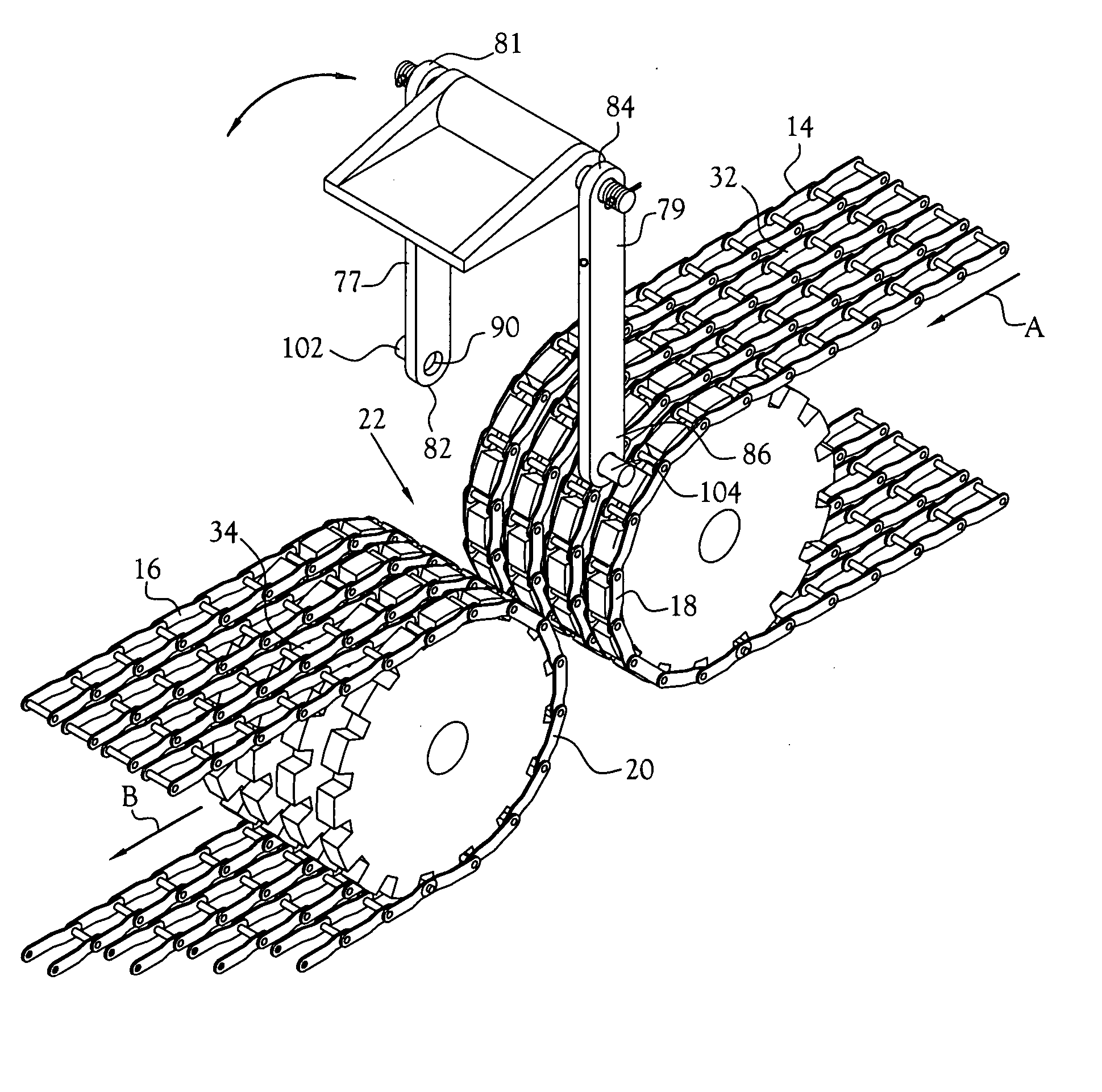
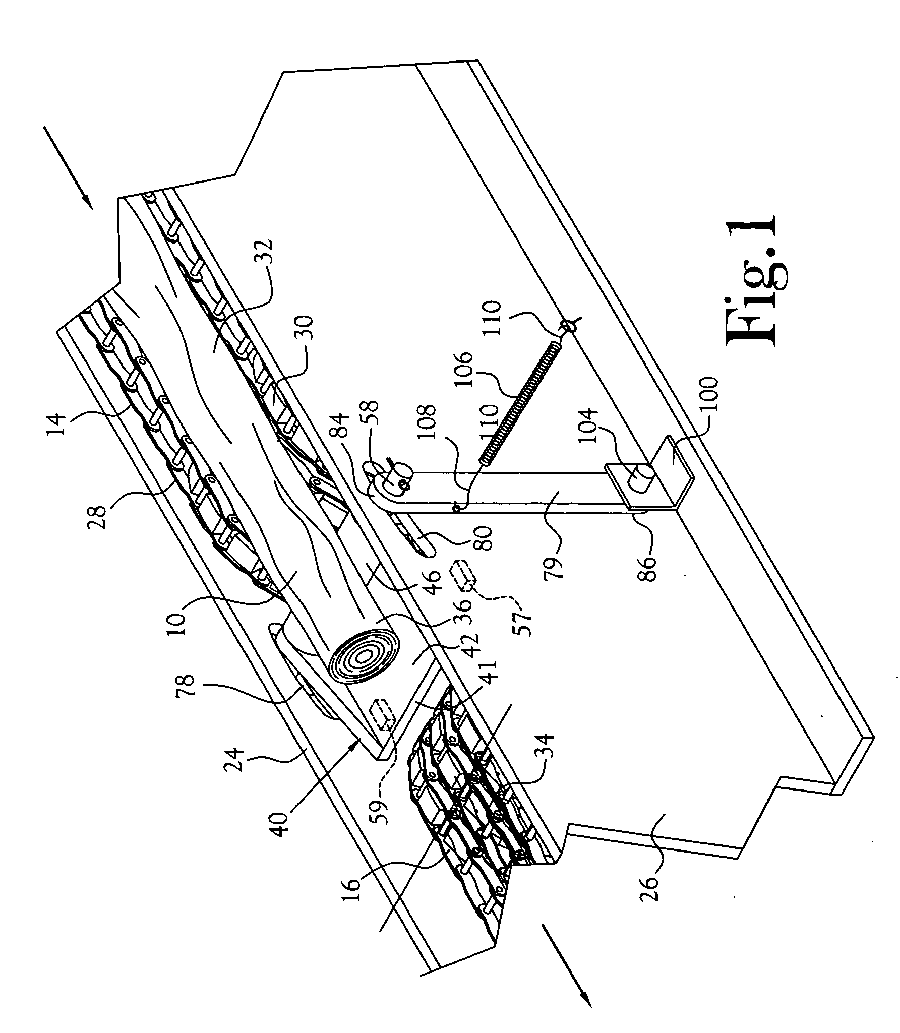
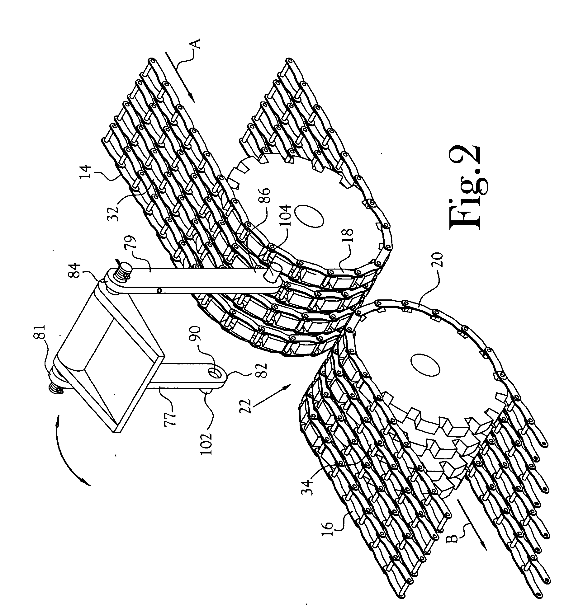
[0023] Referring initially to FIGS. 1 and 2, in a typical mill for converting wood logs to chips, the debarked logs 10 (typical) are discharged by gravity from the debarking drum (not shown) onto a first conveyor 14 and conveyed toward a chipper (not shown). Shortly before reaching the chipper, the logs are transferred from the first conveyor to a second conveyor 16 which completes the transfer of the logs to the chipper. As depicted in FIG. 2, the end 18 of the first conveyor terminates short of, but adjacent to, the end 20 of the second conveyor. These ends of the conveyors are spaced apart and define an open gap 22 therebetween which extends substantially fully across the width of the conveyors. As seen in FIG. 1, the conveyors are supported by superstructure which typically includes first and second support beams 24,26 disposed along opposite sides 28,30 of the conveyors and spaced apart by a distance sufficient to receive the conveyors therebetween. Typically, the gap between t...


PUM


Abstract

Apparatus for self-clearing of clogs developed between adjacent ends of upstream and downstream conveyors adapted to carry products thereon in the course of transfer of the products past a gap defined between the conveyors. The apparatus comprises a shield disposed between the adjacent ends of the conveyors and adapted to cover less than all of the gap between the conveyors and having a proximal side edge disposed adjacent the end of the downstream conveyor, thereby defining an opening for the discharge of debris from the products being transferred between the conveyors through the opening. The shield is mounted for selected degrees of covering relationship to the gap between the conveyors. Means is provided for biasing the shield toward a position of maximal covering of the gap while permitting automatic movement of the shield toward a position of reduced covering of the gap as a function of the application of a force against said shield occasioned by the initiation of a clog by the products being transferred between the shield and the downstream conveyor.

Description

CROSS-REFERENCE TO RELATED APPLICATIONS [0001] Not Applicable STATEMENT REGARDING FEDERALLY SPONSORED RESEARCH OR DEVELOPMENT [0002] Not Applicable FIELD OF INVENTION [0003] This invention relates to conveyors, and particularly to devices employed to selectively bridge the gap between contiguous ends of two conveyors or conveyor sections. BACKGROUND OF INVENTION [0004] In the manufacture of paper from wood, among the first steps are debarking the logs and conversion of the wood logs into chips which are subsequently cooked (digested) to commence the separation of the wood fibers from other components of the chips. [0005] In a common sequence of operation, the logs are loaded with a crane from a storage yard to a debarking drum where at least a major portion of the bark is removed from each log and thereafter the debarked logs are discharged onto the conveying system to a chipper. This conveying operation to the chipper is commonly designed to spread the logs into loose bundles of tw...

Claims


Application Information

Patent Timeline
Patent Type & Authority Applications(United States)
IPC IPC(8): B07B13/04B65G47/52B65G47/66B65H3/08
CPCB07B13/04B65G47/66B65G47/52
Inventor TEMLER, JAN S.WILLMORE, RUSTYLEE, WILLIE
Owner INT PAPER CO
Why Eureka
Try Eureka