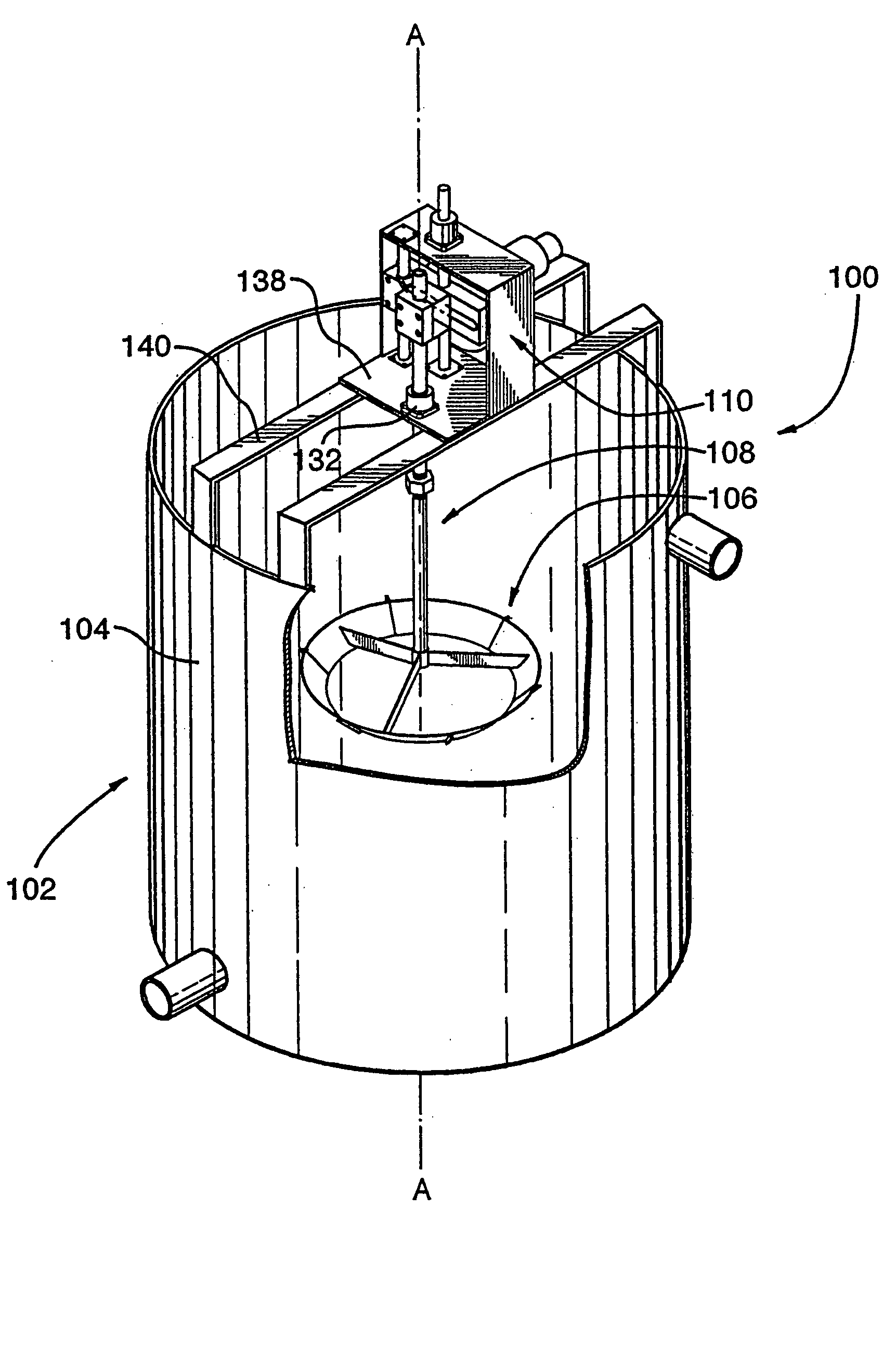
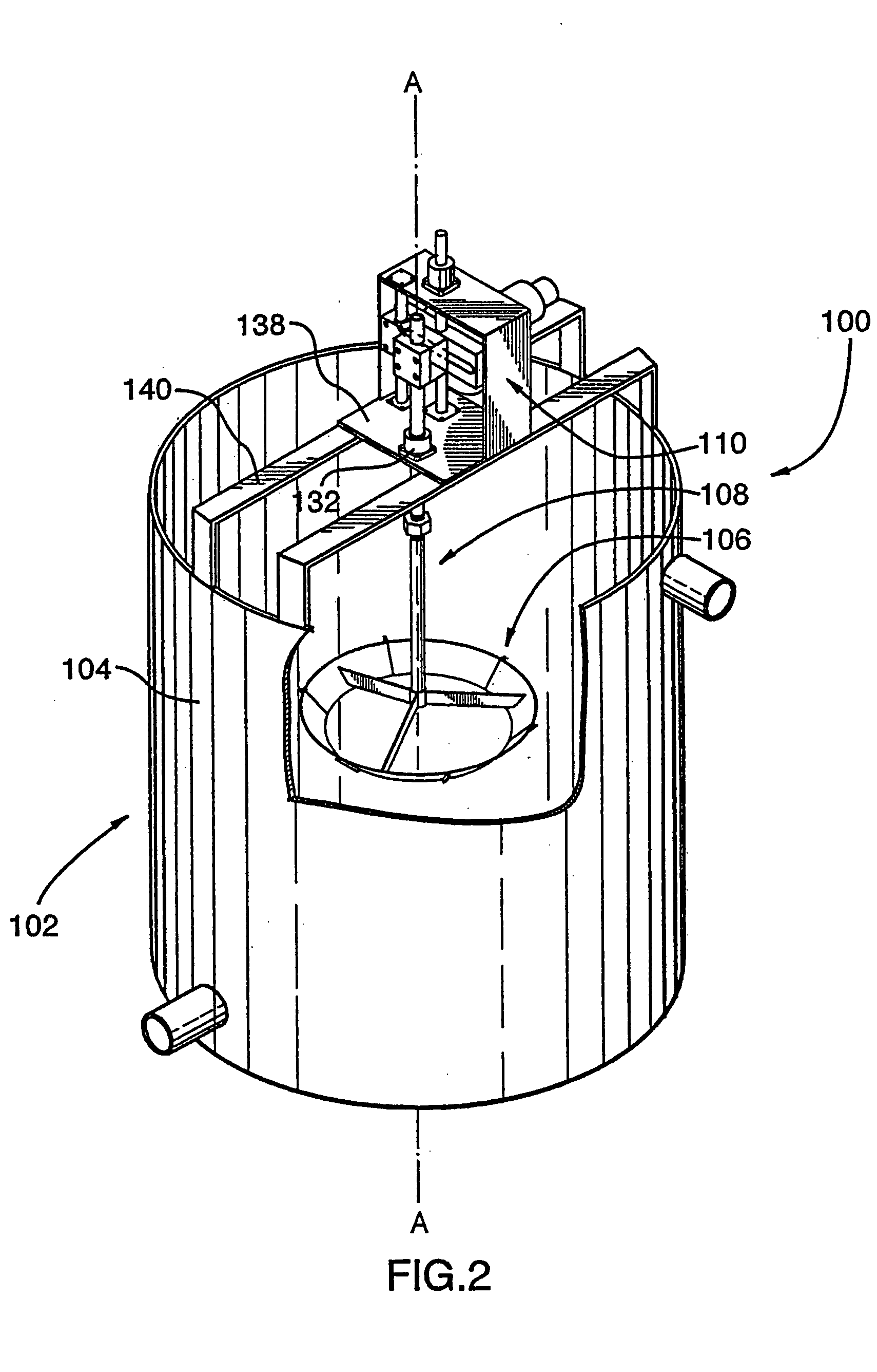
Mixing apparatus

a technology of mixing apparatus and mixing chamber, which is applied in the direction of mixing machines, flotation, solid separation, etc., can solve the problems of adverse effects on economies

Inactive Publication Date: 2005-08-11
ENERSAVE FLUID MIXERS
View PDF28 Cites 12 Cited by
  • Summary
  • Abstract
  • Description
  • Claims
  • Application Information

AI Technical Summary

Benefits of technology

[0025] As yet another aspect of the present invention, the reciprocating means preferably comprises shaft gripping means for gripping the mixer shaft adjacent the top end thereof and effects longitudin

Problems solved by technology

However, the general configurations noted above have been found to provide relatively economical results, and significant variations therefrom can impact adversely upon economies.
Specifically, the relatively large motors employed are required to drive t

Method used


Image

  • Mixing apparatus
  • Mixing apparatus
  • Mixing apparatus

Examples


example 1

[0085] In the known application of the SXEW process previously described, samples were taken from the outfall of each of the primary vessel; secondary vessel; tertiary vessel and settling tank of a respective secondary extraction unit (A) and permitted to separate.

[0086] In a parallel secondary extraction unit (B) (ie processing a pregnant leachate of substantially identical composition), a mixing apparatus in accordance with the present invention (OD=60; ID=48; α=120; S=10; T=0.0333, driven by a 2 hp motor) was substituted for the rotary mixer in the secondary mixing vessel, and samples were again taken from the outfall from each of the primary, second and tertiary mixing vessels, and from the settling tank, and permitted to separate.

[0087] Copper concentration (g / l) was measured in the organic component of each sample, as follows:

(A)(B)30 cpmCu(g / l)Cu (g / l)Primary mixing vessel2.012.01Secondary mixing vessel2.062.06Tertiary mixing vessel2.122.13Settling tank2.142.13

[0088] As w...

example 2

[0089] In a second test, the B line of Example 1 was modified by altering the motor speed of the mixer of the present invention, such that it operated at 45 cycles / minute (T=0.0222).

[0090] Copper concentration (g / l) was again measured, as follows:

(B)[45 cpm]Cu(g / l)Primary mixing vessel2.00Secondary mixing vessel2.08Tertiary mixing vessel2.11Settling tank2.16

[0091] Again, as would be expected, copper concentration from the primary mixing vessel in the B line remained similar to that obtained in the A line (because to that point in the process, mixing is provided by identical rotary mixers). However, unexpectedly, copper concentrations in the outfall from the settling tank from the modified B line showed significant improvement over the A line results (copper recovery improved from 2.14 g / l to 2.16 g / l).

[0092] Without intending to be bound by theory, it is believed the mixing apparatus of the present invention provides mixing currents which [at least in the context of the liquids ...


PUM

PropertyMeasurementUnit
Lengthaaaaaaaaaa
Angleaaaaaaaaaa
Diameteraaaaaaaaaa

Abstract

A mixer apparatus for use with a vessel centered about a longitudinal axis is disclosed. The mixer has a blade which: defines a central head axis; has a first end and a second end. The second end defines an inside blade diameter “ID” and the first end defines an outer blade diameter “OD”. The blade is positioned within and coaxial to the vessel. A scotch yoke, operatively connected to the blade by a shaft, effects reciprocating longitudinal movement of the blade through a stroke “S”, with a duration “T” for each cycle, wherein 175≲0.36×OD2/ID2×S/T≲250 when OD, ID and S are expressed in inches, and T is expressed in minutes.

Description

CROSS-REFERENCE TO RELATED APPLICATIONS [0001] This application is a continuation of Ser. No. 10 / 294,563 filed Nov. 15, 2002, which is a continuation-in-part of PCT / CA 02 / 00528 filed Apr. 17, 2002.BACKGROUND OF THE INVENTION [0002] The present invention generally relates to the field of mineral ore processing, and more particularly, to a mixing apparatus and to uses thereof in the separation of minerals from mineral bearing ores. [0003] Processes are known in the prior art which provide for the separation of minerals from mineral bearing ores. [0004] For example, in known processes used for the separation of copper from copper bearing ores, illustrated diagrammatically in FIG. 1, non oxidized ores 20 (which might contain as little as 0.5% copper, and typically contain iron sulfides) are processed in a crusher 22, with water 24, to form a slurry 26. The slurry 26 is then transferred to a flotation cell 28, and subjected to physical action, specifically, air sparging and mixing. As a ...

Claims


Application Information

Patent Timeline
IPC IPC(8): B01F11/00B01F15/00B03D1/16
CPCB01F11/0082B03D1/1412B01F15/00467B01F15/00915B01F2215/0409B01F2215/0422B01F2215/0431B01F2215/0454B03D1/1418B03D1/16C22B3/0005C22B3/02C22B9/106B03D1/1462B01F11/0091Y02P10/20C22B3/26B01F31/449B01F31/441B01F35/325B01F35/55
Inventor HAUGHTON, GARYBEHR, MARTINOSTROWSKI, TOM
Owner ENERSAVE FLUID MIXERS
Why Eureka
Try Eureka