Miniature infusion pump

a technology of infusion pump and miniature body, which is applied in the field of infusion pump, can solve the problems of large current consumption, large current consumption of infusion device, and additional drawbacks of electric motors

Inactive Publication Date: 2005-08-11
OZERI SHAUL +1
View PDF4 Cites 126 Cited by
  • Summary
  • Abstract
  • Description
  • Claims
  • Application Information

AI Technical Summary

Benefits of technology

[0012] The device's housing is small, lightweight and watertight. The de

Problems solved by technology

These devices contain electrical motors which are relatively large and heavy.
Since dosages are given at discrete intervals over a period of time, each time the processing circuit activates the motor it consumes large current to operate.
The in addition to the disadvantages in size, weight and power consumption of existing medication pumps, theses devices also suffer from an additional drawback which stems from the principles according to which they operate.
The accuracy of these devices is therefore hard to control

Method used


Image

  • Miniature infusion pump
  • Miniature infusion pump
  • Miniature infusion pump

Examples


second embodiment

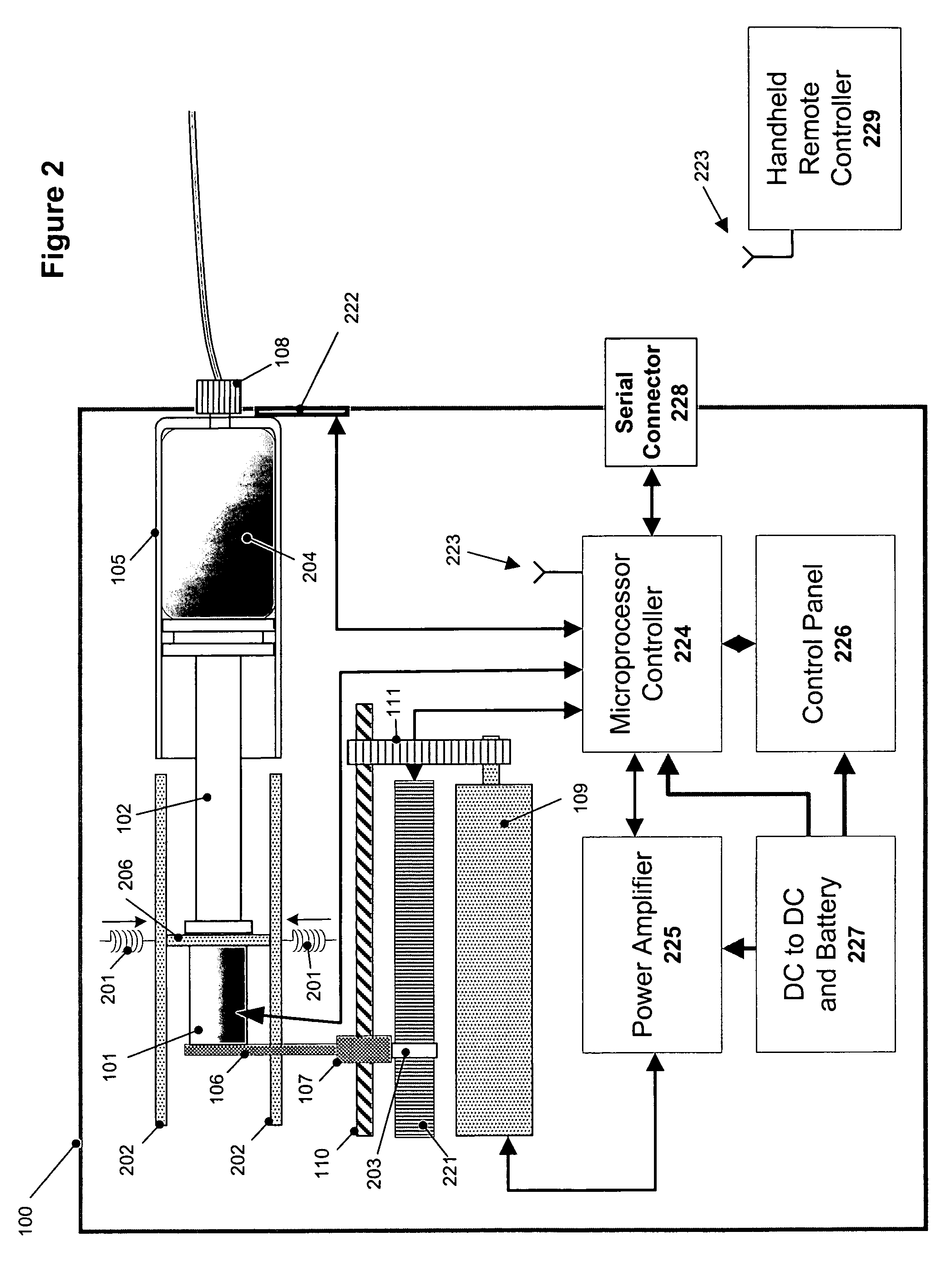
[0038] The constitution of the stopper 303 and its method of operation are illustrated in FIG. 4. The stopper 303 comprises of an upper holding cylinder 402 and a lower holding cylinder 403 which are connected by a cylinder internal spring 401 and a shape memory alloy (SMA) actuator 404. The spring 401 allows the two cylinders 402, 403 to reduce and expend their relative proximity and allows flexibility in the amount of pressure that the cylinders 402, 403 apply on the guiding walls 202. The SMA actuator 404 contracts in length when electrically heated and easily returns to its normal size as it cools back to an ambient temperature. In the normal state of the stopper 303 the cylinders 402, 403 are pressed against the guiding walls 202 and resist movement whenever the PZT actuator 101 expends and ensure that the full length of the PZT actuator's 101 expansion is in the direction of the plunger 102. After the PZT actuator 101 contracted back to its normal size the SMA actuator 404 rec...

first embodiment

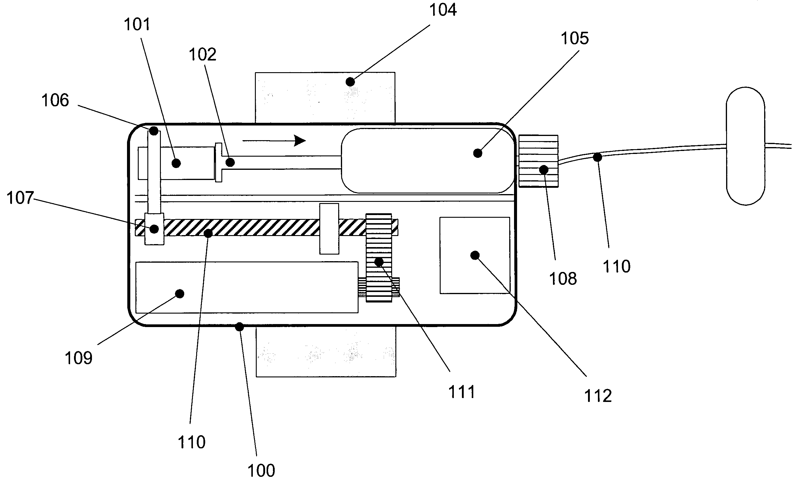
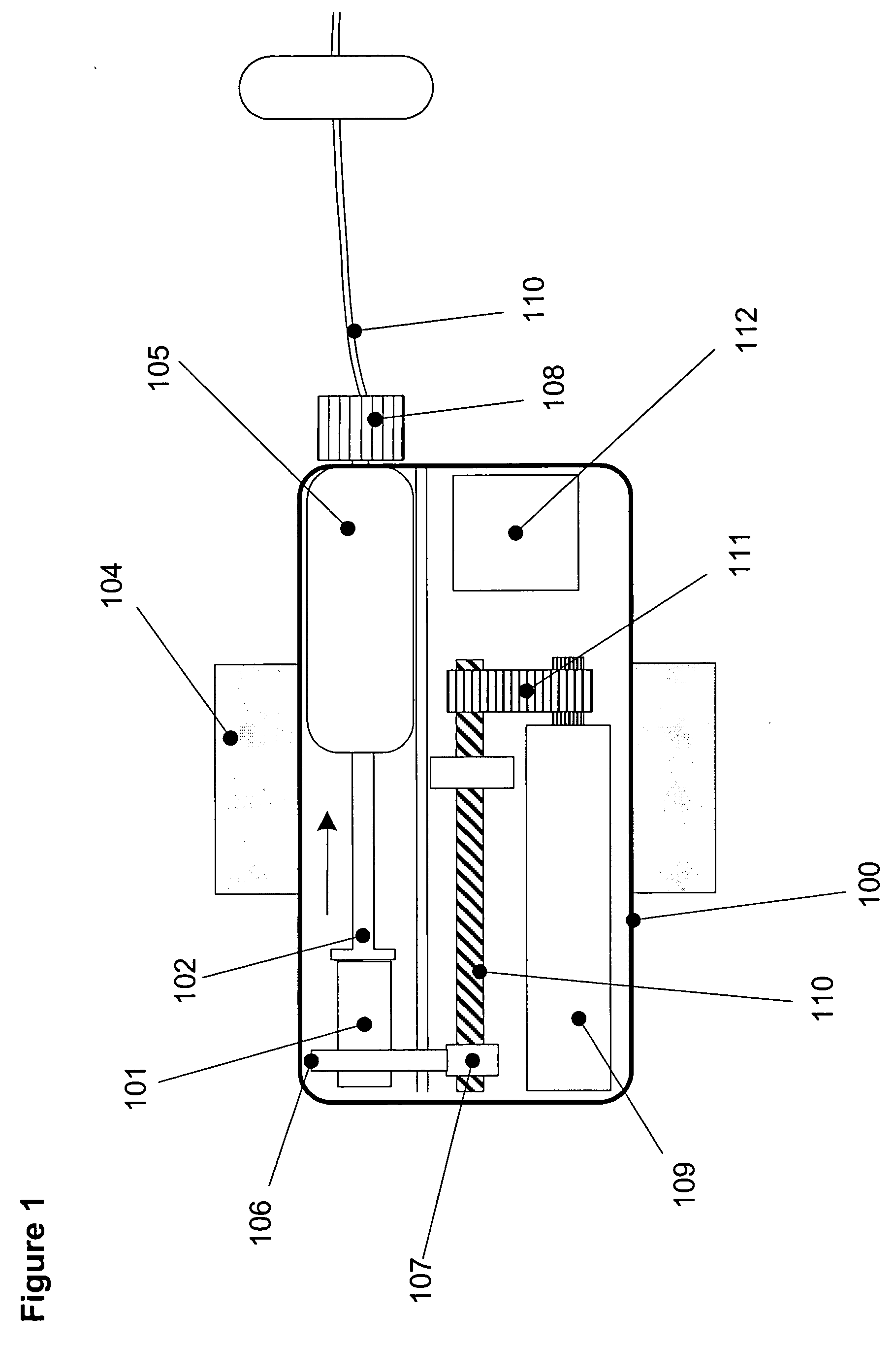
[0040] The manual operation of loading the syringe includes the following steps: first, the guiding walls 202, which are held in place by springs 201, are released by the user and then the nut lever 106 is released from the screw nut 107. The user may them return the screw nut 107 back into its initial position at the far end of the lead screw 110 and the nut lever 106 can then reconnect to the screw nut 107. Returning the screw nut 107 to its initial position may be achieved by screwing it back on the lead screw 110, or by using a split nut mechanism which allows for easily changing the position of the screw nut 107 on the lead screw 110. The user removes the syringe 105, fills it with the appropriate chemical reagents and places it back into place in the device. The device is then ready to be turned on and put into use.

[0041] The manual operation of loading the syringe according to the second invention is illustrated in FIG. 5. The guiding walls 202, which are held in place by sp...


PUM


Abstract

A micro-pump that supplies medication from a reservoir to a patient through a flexible tube is disclosed. The pump, which is especially suitable but not confined to delivering insulin to diabetic patients, is small and light enough to be attached to the body using adhesive plaster or to be strapped to the body in any other manner. In the preferred embodiment the pump mechanism comprises a lead screw, a weak force rotating element, an actuator, and a high force holding element. The device also includes a processing circuitry for controlling and monitoring the drive mechanism, a force sensor to measure medication pressure which generates indicative signals to the processing circuitry, a sensor for tracking the position of the syringe plunger, and a remote control unit.

Description

BACKGROUND OF THE INVENTION [0001] The present invention relates to the field of infusion pumps for controlled delivery of medication to patients, more specifically to an infusion pump with an improved minute lightweight drive mechanism. [0002] Infusion pumps deliver a volumetrically controlled medication to the patient over a period of time. A processing circuitry controls the periodic delivery of dosages of medication to a patient at predetermined rates. Infusion pumps often contain an electrical motor which rotates a lead-screw; the rotation of the lead-screw causes a nut to linearly move along it. The nut pushes a plunger through a syringe or a cartridge internal to the pump that causes medication to move from the syringe to the patient along the infusion path. [0003] Prior art of Infusion pumps contain a large electrical motor which are strong enough to rotate the lead-screw against the opposing pressure of the medication inside the syringe. Such mechanism is described, for exa...

Claims


Application Information

Patent Timeline
IPC IPC(8): A61M5/142A61M5/145A61M37/00
CPCA61M5/14244A61M2205/3576A61M2205/0266A61M5/1456
Inventor OZERI, SHAULOZERI, JEHONATAN
Owner OZERI SHAUL
Why Eureka
Try Eureka