Hood tilt mechanism for curved glass processing

a technology of curved glass and tilt mechanism, which is applied in the field of glass forming and transport mechanisms to shape curved glass, can solve the problems of large tendency to chip or crack, complex shape of glass components used in automobiles, and mis-shaped glass, so as to reduce the cycle time of glass forming, scrap, and maintenance time

Inactive Publication Date: 2005-08-18
AUTOMOTIVE COMPONENTS HOLDINGS
View PDF24 Cites 24 Cited by
  • Summary
  • Abstract
  • Description
  • Claims
  • Application Information

AI Technical Summary

Benefits of technology

[0008] An advantage of the present invention is that, since the hood can tip, the glass can be brought into a vacuum mold on a hot ring at a better orientation to the mold, without requiring the use of an articulated hot ring. By eliminating the need for an articulated hot ring, cycle time for glass forming, scrap, and maintenance time can be reduced.
is that, since the hood can tip, the glass can be brought into a vacuum mold on a hot ring at a better orientation to the mold, without requiring the use of an articulated hot ring. By eliminating the need for an articulated hot ring, cycle time for glass forming, scrap, and maintenance time can be reduced.

Problems solved by technology

Glass components used in automobiles, such as windshields, are often complex shaped parts.
So, if the hood is mis-adjusted, the glass can be mis-shaped.
Since it is glass, and so somewhat brittle, the glass must be at the proper angle when dropped onto the pads of the shuttle or it has a greater tendency to chip or crack.
For particularly complex shaped glass, such as vehicle windshields with complex curvature, assuring the proper angle can be difficult, especially since, for the complex shaped glass, this angle can be different than that needed in the mold.
If the placement of the glass on the cooling shuttle does not allow for the glass to contact all of the shuttle pads essentially at the same time, the glass will have a tendency to chip and crack.
Since conventionally, the tilt of the hood is fixed, the glass tilt relative to the shuttle pads cannot be adjusted while the hood is moving the glass from the cold ring to the shuttle.
Because of this, the orientation of the glass as it is brought into the vacuum mold would not be optimum.
But articulated hot rings are generally not desirable if a non-articulated hot ring can be employed instead.

Method used


Image

  • Hood tilt mechanism for curved glass processing
  • Hood tilt mechanism for curved glass processing
  • Hood tilt mechanism for curved glass processing

Examples


Embodiment Construction

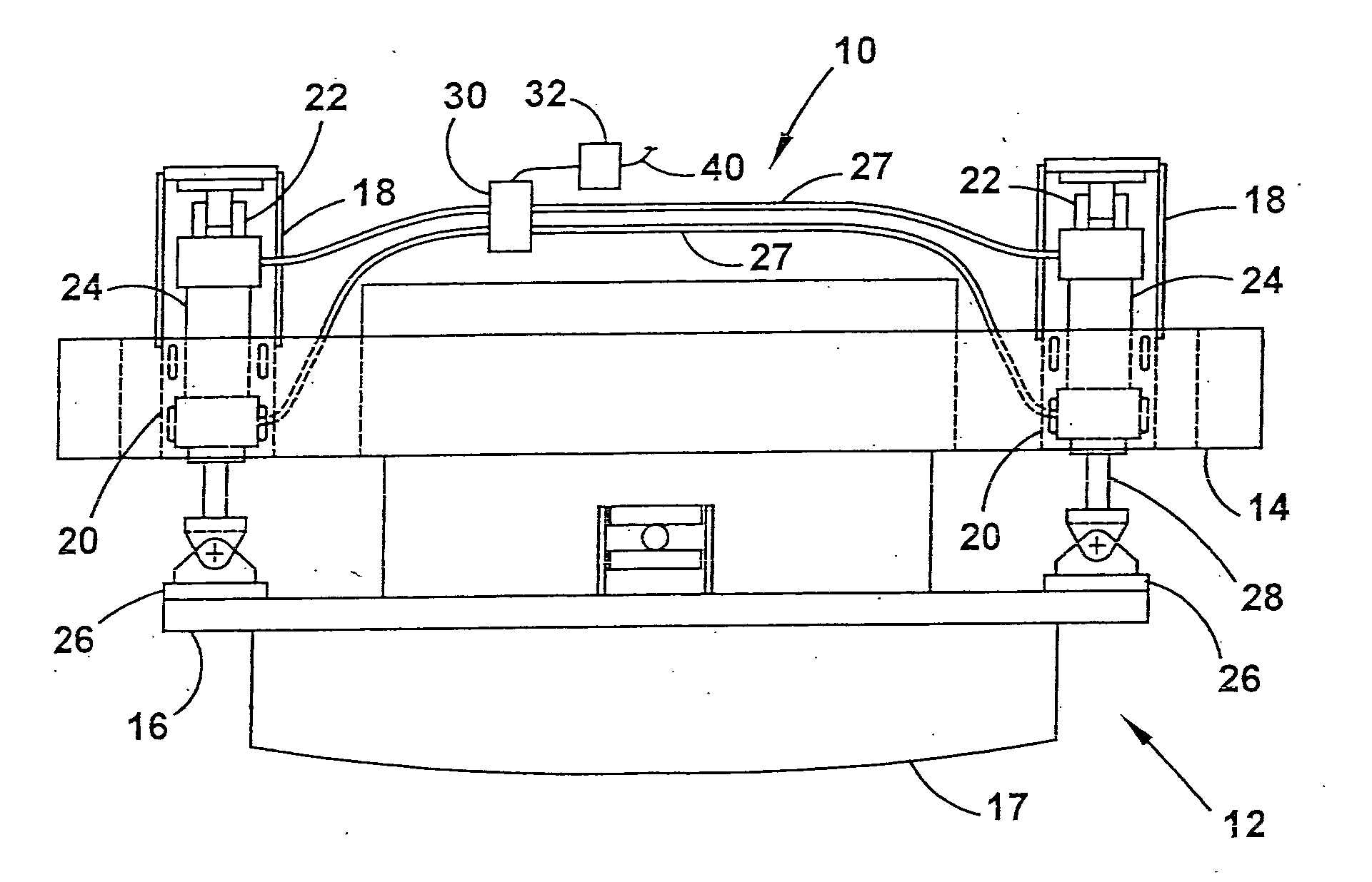
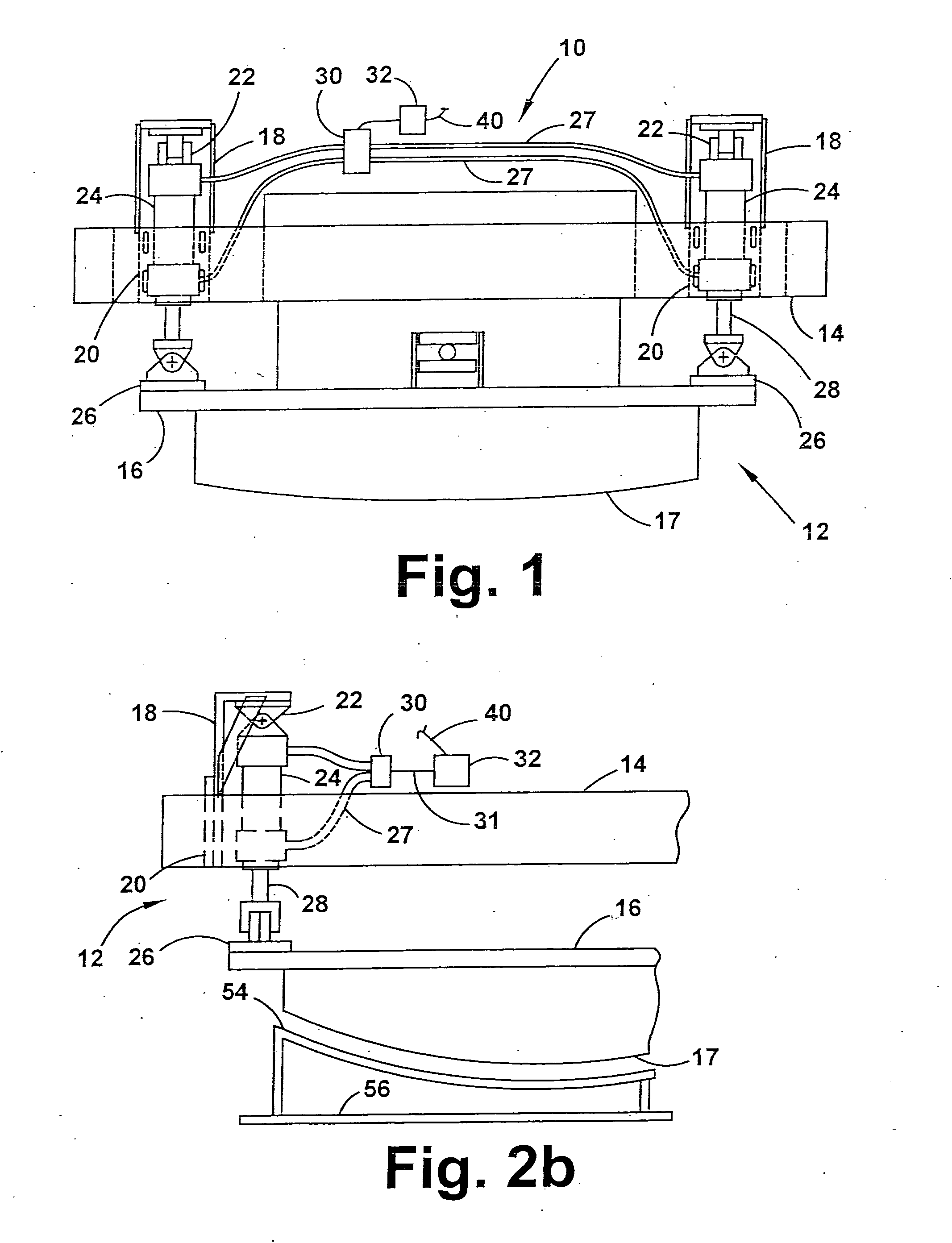
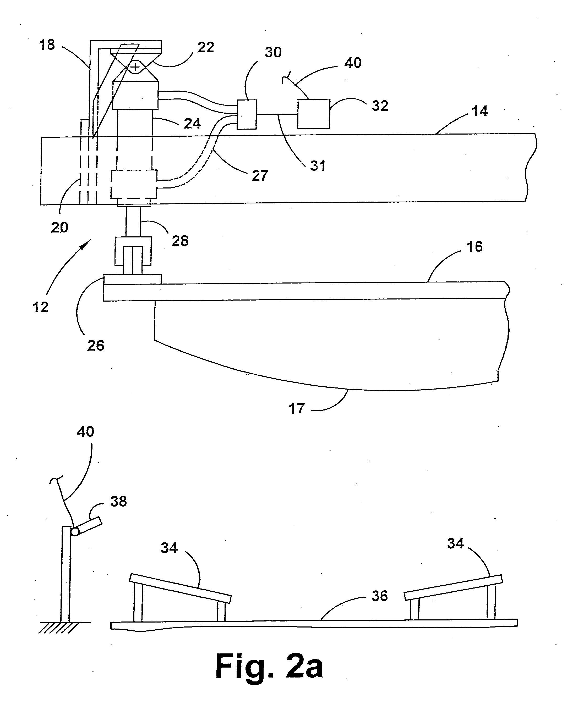
[0012]FIGS. 1 and 2a-2d illustrate a hood assembly 12 portion of a glass forming assembly 10. The hood assembly 12 includes a hood lift superstructure 14, which is mounted to the glass forming assembly 10 and is only movable in the horizontal and vertical direction, and a hood frame 16, which mounts to and is supported by the hood lift superstructure 14. The bottom side 17 of the hood frame 16 is shaped to receive the glass and hold it by vacuum pressure. A first end of the hood frame 16 is pivotally mounted to the hood lift superstructure 14, while a second end is mounted to and supported by the hood lift superstructure 14 via a pair of hood tilt mechanisms 18.

[0013] The hood tilt mechanisms 18 each include an adjustable hood lift mounting bracket 20, which is fastened to the hood lift superstructure 14 via slotted holes that allow for accurate alignment of the hood tilt mechanism 18 relative to the hood lift superstructure 14. Each of the hood tilt mechanisms 18 also include an a...


PUM

PropertyMeasurementUnit
angleaaaaaaaaaa
glass formingaaaaaaaaaa
shapeaaaaaaaaaa

Abstract

A glass forming assembly for forming complex shaped glass, with the glass forming assembly having a hood assembly including a hood lift superstructure movable horizontally back and forth over a cold ring and a cooling shuttle and movable vertically relative to the cold ring and the cooling shuttle, and a hood frame supported by the hood lift superstructure by a hood tilt mechanism. The hood tilt mechanism includes an air cylinder assembly actuable to tilt the hood frame relative to the hood lift superstructure, which allows for proper orientation of the glass prior to dropping it on the cooling shuttle, thus allowing for reduced glass chipping and cracking.

Description

CROSS REFERENCE TO RELATED APPLICATIONS [0001] This application claims the benefit of U.S. nonprovisional patent application Ser. No. 10 / 205,065, filed Jul. 25, 2002, which is incorporated herein by reference.BACKGROUND OF INVENTION [0002] The present invention relates to glass forming and transport mechanisms, and in particular to glass forming and transport mechanisms to shape curved glass, such as, for example, glass in vehicles. [0003] Glass components used in automobiles, such as windshields, are often complex shaped parts. During the shaping process, hot glass enters a vacuum mold and is shaped close to its final shape. The glass needs to be brought into the mold at a predetermined angle on a hot ring in order to allow for proper shaping. The mold drops down and picks up the glass off of the hot ring via vacuum pressure. The hot ring is removed, and then a cold ring is brought under the glass, with the glass released onto the cold ring from the mold. The glass is then picked u...

Claims


Application Information

Patent Timeline
Patent Type & Authority Applications(United States)
IPC IPC(8): C03B23/03C03B35/14
CPCC03B35/145C03B23/03
Inventor MOULDING, FRANK E.SCOTT, LARRY J. JR.CROFT, ROBERTVANDERGRIFT, RONALD
Owner AUTOMOTIVE COMPONENTS HOLDINGS
Why Eureka
Try Eureka