Gasket and drum-type washing machine having the same

Active Publication Date: 2005-08-18
LG ELECTRONICS INC
3 Cites 34 Cited by

AI-Extracted Technical Summary

Problems solved by technology

Meanwhile, drum-type washing machines, in which the drum and tub are disposed horizontally, tend to avoid damaging and raveling the laundry and consume less water while achieving a washing effect of beating and rubbing.
In addition, as the drum 30 cont...

Method used

[0033] In addition to the above functions, the gasket according to the present invention prevents laundry from becoming wedged (or lodged) between the drum and the gasket itself, specifically, between the annular lip 520 of the gasket 500 and the drum entrance 330. This phenomenon occurs most often while the drum 300 is driven during normal operation, because of its proximity of the annular lip 520, and the phenomenon is exacerbated when the drum is rotated at high speed, for example, during a dewatering cycle to separate water from the laundry using centrifugal force. Therefore, the gasket 500 according to the present invention is provided with a laundry kicker 530, protruding inwardly from a predetermined portion of the annular lip 520, for dislodging laundry that has become wedged between the annular lip and the drum entrance 330 and for preventing further occurrences of such wedging. Preferably, the laundry kicker 530 is disposed at the uppermost point of the gasket 500 as installed in the washing machine, i.e., at the apex of the annular lip 520.
[0034] In the event that laundry becomes wedged between the drum 300 and the gasket 500, the laundry kicker 530 returns (or kicks) the laundry back into the drum's interior, using the drum's own rotational force. That is, during normal operation in which the drum 300 is rotated forward and reversely, when laundry becomes wedged between an inner surface of the annular lip 520 and the rotating drum, the wedged laundry will be lifted by the rotational force of the drum and slide along the inner surface of the annular lip until reaching the laundry kicker 530, which has a structure for guiding the laundry away from the gasket 500, to return the previously wedged laundry to the drum and be reintroduced to the bulk of the laundry. To facilitate the laundry's return, the laundry kicker 530 has a distal (or inward) end on which a catch 531 having a predetermined thickness is formed to protrude into the drum 300. The laundry kicker 530 extends from the annular lip 520 to a point beyond the forward edged of the drum entrance, to span a gap between annular lip and the drum entrance, whereby the wedged laundry rotating with th...

Benefits of technology

[0016] To achieve these objects and other advantages in accordance with the present invention, as embodied and broadly described herein, a gasket coupled between a cabinet of a drum-type washing machine including a drying duct for providing a drying function and a tub disposed inside the cabinet includes an annular lip, protruding inwardly from an inner circumference ...

Abstract

A gasket and washing machine having the same prevent laundry from becoming wedged between a drum and a gasket for preventing water leakage. The gasket is coupled between a cabinet of a drum-type washing machine including a drying duct for providing a drying function and a tub disposed inside the cabinet. The gasket includes an annular lip, protruding inwardly from an inner circumference of the gasket, for preventing foreign matter from entering a space existing between the tub and a rotating drum, and a laundry kicker, protruding inwardly from a predetermined portion of the annular lip, for dislodging laundry that has become wedged between the annular lip and the rotating drum.

Application Domain

Other washing machinesWashing machine with receptacles +2

Technology Topic

InjectorForeign matter +3

Image

  • Gasket and drum-type washing machine having the same
  • Gasket and drum-type washing machine having the same
  • Gasket and drum-type washing machine having the same

Examples

  • Experimental program(1)

Example

[0027] Reference will now be made in detail to the preferred embodiment of the present invention, examples of which are illustrated in the accompanying drawings. Throughout the drawings, like elements are indicated using the same or similar reference designations where possible.
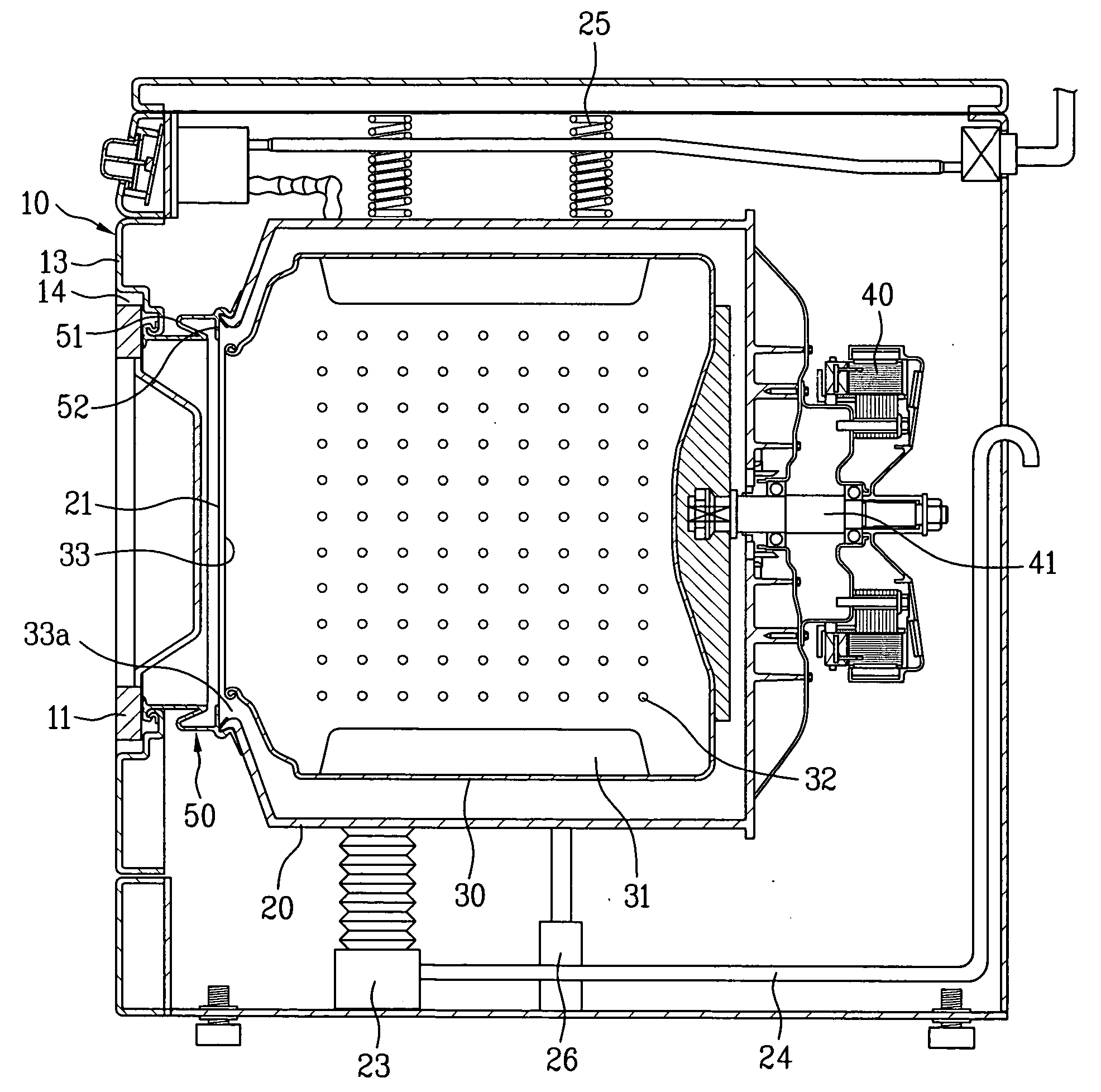
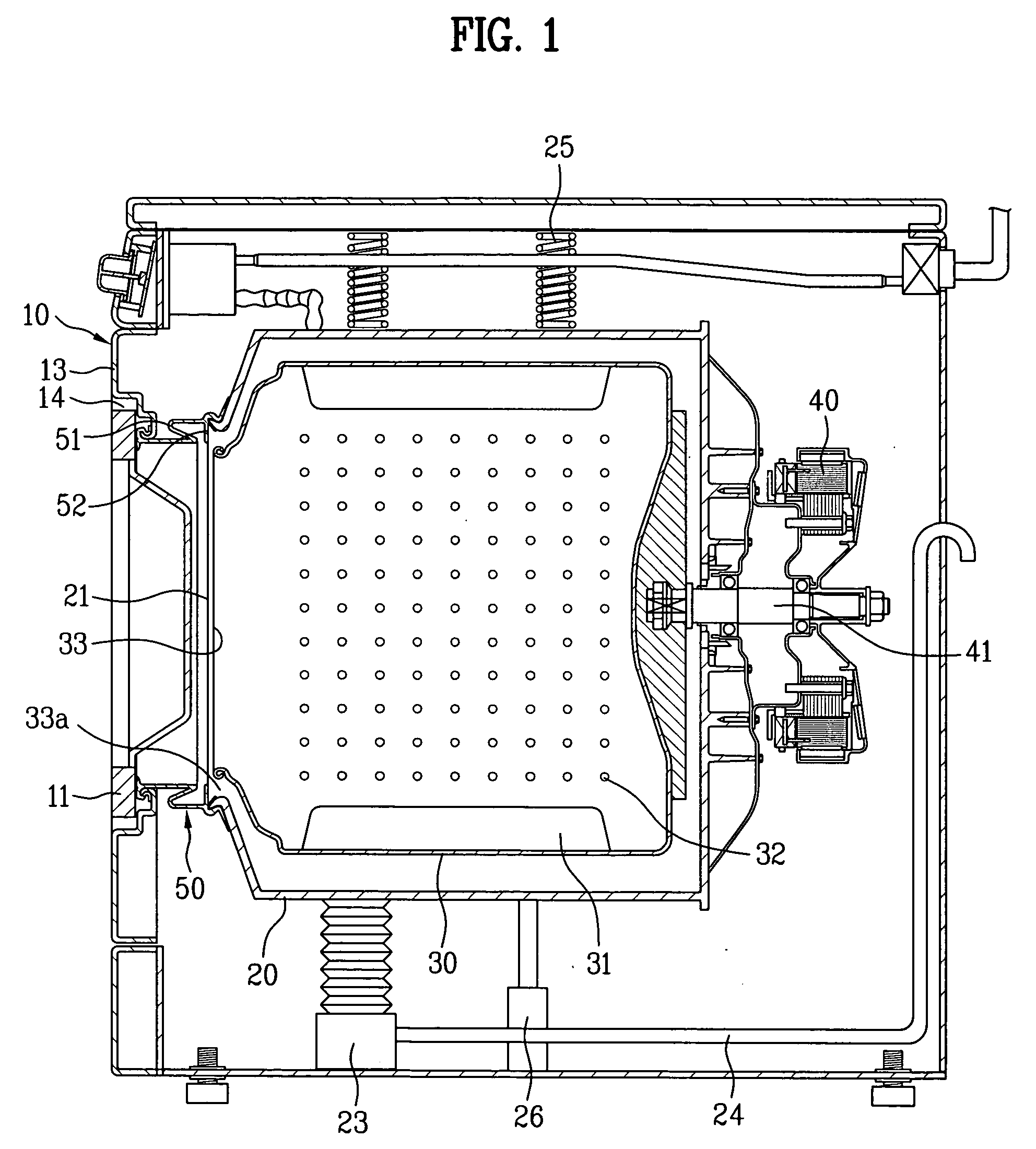
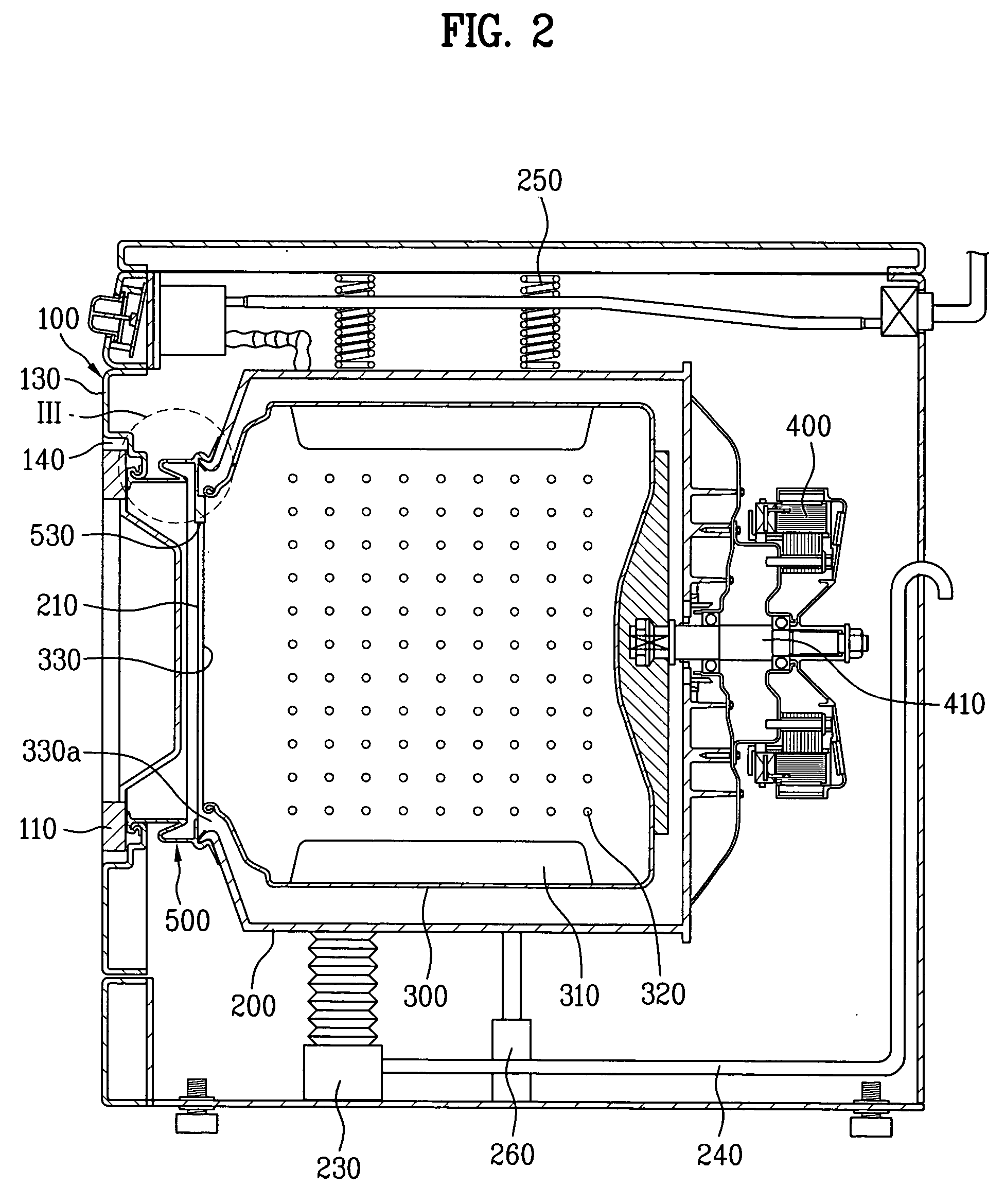
[0028] Referring to FIG. 2, a drum-type washing machine according to the present invention comprises a cabinet 100 forming an exterior of the washing machine and having a forward opening 140, formed in a front panel 130 of the cabinet, for loading and retrieving laundry via a door 110; a tub 200, suspended within the cabinet 100, having an entrance 210 for communicating with the forward opening of the front panel; and a drum 300, rotatably installed within the tub and provided with a multitude of perforations 320 to let water pass from the tub to the drum, having a cylindrical shape with an entrance 330 at its front end to communicate with the tub entrance. A laundry opening, through which laundry can be loaded into and retrieved from the drum 300, is thus formed by a combination of the forward opening 140, tub entrance 210, and drum entrance 330. A drain pump 230 and a drain hose 240 are installed under the tub 200 for draining washing water supplied to the tub.
[0029] A rotating means 400, such as an induction or BLDC motor for rotating the drum 300 and including a rotational shaft 410 centrally coupled to the rear of the drum, is installed behind the tub 200 and rotates the drum forward and reversely according to the motor's rotational direction. At least one lifter 310 is provided to an inner wall of the drum 300 to assist the washing action by repeatedly lifting the laundry to a predetermined height as the drum is rotated and then allowing the lifted laundry to fall from the predetermined height.
[0030] To attenuate vibration generated during operation of the drum-type washing machine, the tub 200 is supported by an elastic means, including a spring 250 disposed above the tub and a damper 260 disposed below the tub.
[0031] According to the present invention, a drum-type washing machine as described above is provided with a gasket 500 as shown in FIGS. 3 and 4. The gasket, having an essentially annular shape, is provided between the cabinet 100 having a front panel 130 and the tub 200 installed behind the front panel, essentially connecting the entrance 210 of the tub to the forward opening 140 of the front panel. The gasket of the present invention is multipurpose. To prevent water leakage, the gasket 500 has a front rim 501 coupled to the front panel 130 of the cabinet 100 and a rear rim 502 coupled to the entrance 210 of the tub 200, thus closing a gap between the cabinet and tub. To prevent a transfer of vibration to the cabinet 100, the gasket 500 includes a shock absorber 510 having an annular shape corresponding to that of the gasket, in which a bent portion is formed between the front and rear rims 501 and 502 of the gasket by shaping a predetermined length of the gasket material into a U-shaped bend. The shock absorber 510 is preferably formed of a soft, pliable material to absorb vibration appearing in the tub 200, by contracting, expanding, and twisting accordingly.
[0032] The gasket 500 also serves to prevent laundry and foreign matter from entering or becoming lodged in a space 330a, the entrance to which is located between the tub entrance 210 and the drum entrance 330. Therefore, an annular lip 520, protruding inwardly from a rearward inner wall of the gasket 500, is provided. Preferably, the annular lip 530 is integrally formed with the gasket 500 and protrudes inwardly from the rear rim 502, i.e., behind the shock absorber 510. Accordingly, the cutoff part 520 extends from the tub entrance 210 toward the drum entrance 330.
[0033] In addition to the above functions, the gasket according to the present invention prevents laundry from becoming wedged (or lodged) between the drum and the gasket itself, specifically, between the annular lip 520 of the gasket 500 and the drum entrance 330. This phenomenon occurs most often while the drum 300 is driven during normal operation, because of its proximity of the annular lip 520, and the phenomenon is exacerbated when the drum is rotated at high speed, for example, during a dewatering cycle to separate water from the laundry using centrifugal force. Therefore, the gasket 500 according to the present invention is provided with a laundry kicker 530, protruding inwardly from a predetermined portion of the annular lip 520, for dislodging laundry that has become wedged between the annular lip and the drum entrance 330 and for preventing further occurrences of such wedging. Preferably, the laundry kicker 530 is disposed at the uppermost point of the gasket 500 as installed in the washing machine, i.e., at the apex of the annular lip 520.
[0034] In the event that laundry becomes wedged between the drum 300 and the gasket 500, the laundry kicker 530 returns (or kicks) the laundry back into the drum's interior, using the drum's own rotational force. That is, during normal operation in which the drum 300 is rotated forward and reversely, when laundry becomes wedged between an inner surface of the annular lip 520 and the rotating drum, the wedged laundry will be lifted by the rotational force of the drum and slide along the inner surface of the annular lip until reaching the laundry kicker 530, which has a structure for guiding the laundry away from the gasket 500, to return the previously wedged laundry to the drum and be reintroduced to the bulk of the laundry. To facilitate the laundry's return, the laundry kicker 530 has a distal (or inward) end on which a catch 531 having a predetermined thickness is formed to protrude into the drum 300. The laundry kicker 530 extends from the annular lip 520 to a point beyond the forward edged of the drum entrance, to span a gap between annular lip and the drum entrance, whereby the wedged laundry rotating with the drum is forced from (or escapes) its wedged position. Accordingly, the laundry kicker 503 is stepped to enhance its laundry-collecting capability. That is, if the laundry kicker 530 were to be formed to have one thickness, i.e., consistent with that of the annular lip 520, the wedged laundry would tend to slide behind the annular lip as the drum 300 rotated, thus bypassing the laundry kicker, and may fail to be returned to the drum. Accordingly, the laundry kicker 530 includes a stepped portion formed between an inward surface of the annular lip 520 and an inward surface of the catch 531.
[0035] Referring to FIGS. 5 and 6, a horizontal cross-section of the laundry kicker 530 decreases in width toward its tip, to impart the laundry kicker 530 with a tapered lower portion. That is, the laundry kicker 530 preferably has lower sides 530a formed at a predetermined angle with respect to its upper sides 530b and includes chamfered faces 531a formed on the rearward edges of the upper and lower sides. This structure facilitates a smooth return of wedged laundry to the drum 300. That is, as the drum 300 rotates and the wedged laundry rises to meet the laundry kicker 530, the lower sides 530a gently pull the wedged laundry from its wedged position, to allow the laundry to drop into the drum's interior, thereby guiding the laundry back into the drum. Since the laundry kicker 530 is symmetrical along a vertical plane perpendicular to an inner surface of the annular lip 520 of the gasket 500, its structure is compatible with either rotational direction of the drum 300.
[0036] During operation of a washing machine adopting the gasket of the present invention, if laundry becomes wedged between the annular lip 520 and the drum entrance 330, the laundry is raised to a point on the circumference of the annular lip under the force of the rotating drum, i.e., to the location of the laundry kicker 530, the laundry comes into contact with the laundry kicker and escapes from its wedged position to be guided along the lower sides 530a and the chamfered faces of the catch 531, and then is dropped to be collected in the drum 300.
[0037] By adopting a gasket according to the present invention, an annular lip prevents laundry from entering a space between the tub and the drum. Furthermore, the laundry kicker provided to the gasket removes laundry wedged between the gasket and the drum entrance and prevents further incidence of laundry becoming similarly wedged, and therefore, in addition to providing damage prevention benefits to both the laundry and the gasket itself, the laundry kicker also prevents such wedging from causing noise and vibration, which prevents overloading of the motor and thus prolongs the life of the washing machine.
[0038] It will be apparent to those skilled in the art that various modifications and variations can be made in the present invention without departing from the spirit or scope of the invention. Thus, it is intended that the present invention cover such modifications and variations, provided they come within the scope of the appended claims and their equivalents.

PUM

no PUM

Description & Claims & Application Information

We can also present the details of the Description, Claims and Application information to help users get a comprehensive understanding of the technical details of the patent, such as background art, summary of invention, brief description of drawings, description of embodiments, and other original content. On the other hand, users can also determine the specific scope of protection of the technology through the list of claims; as well as understand the changes in the life cycle of the technology with the presentation of the patent timeline. Login to view more.
Why Eureka
Try Eureka