Liquid tank liner connection

a technology for connecting pipes and liquid tanks, applied in the direction of linings/internal coatings, water heaters, packaging, etc., can solve the problems of cumbersome connection of replacement pipes and difficult installation

Inactive Publication Date: 2005-08-18
AQUA TECH INC
View PDF5 Cites 9 Cited by
  • Summary
  • Abstract
  • Description
  • Claims
  • Application Information

AI Technical Summary

Benefits of technology

[0003] The present invention provides a connection to easily mount a top portion of a flexible, non-molded liner to an inner surface of a tank containing a liquid. The connection employs a plate having at least two outwardly projecting studs and at least one liquid conducting tube passing through the plate. The upper portion of the flexible, non-molded liner is pressed between the plate and the inner surface of the tank adjacent an annular opening. A tank head flange or an externally threaded pipe is welded to an outside of the tank adjacent the annular opening. A flange cap or threaded insert is tightened down over the studs to lock the flexible liner in place.

Problems solved by technology

However, the connection of a replacement liner is cumbersome and difficult to install.

Method used


Image

  • Liquid tank liner connection
  • Liquid tank liner connection
  • Liquid tank liner connection

Examples


Embodiment Construction

[0012] Throughout the following detailed description, the same reference numerals refer to the same elements in all figures.

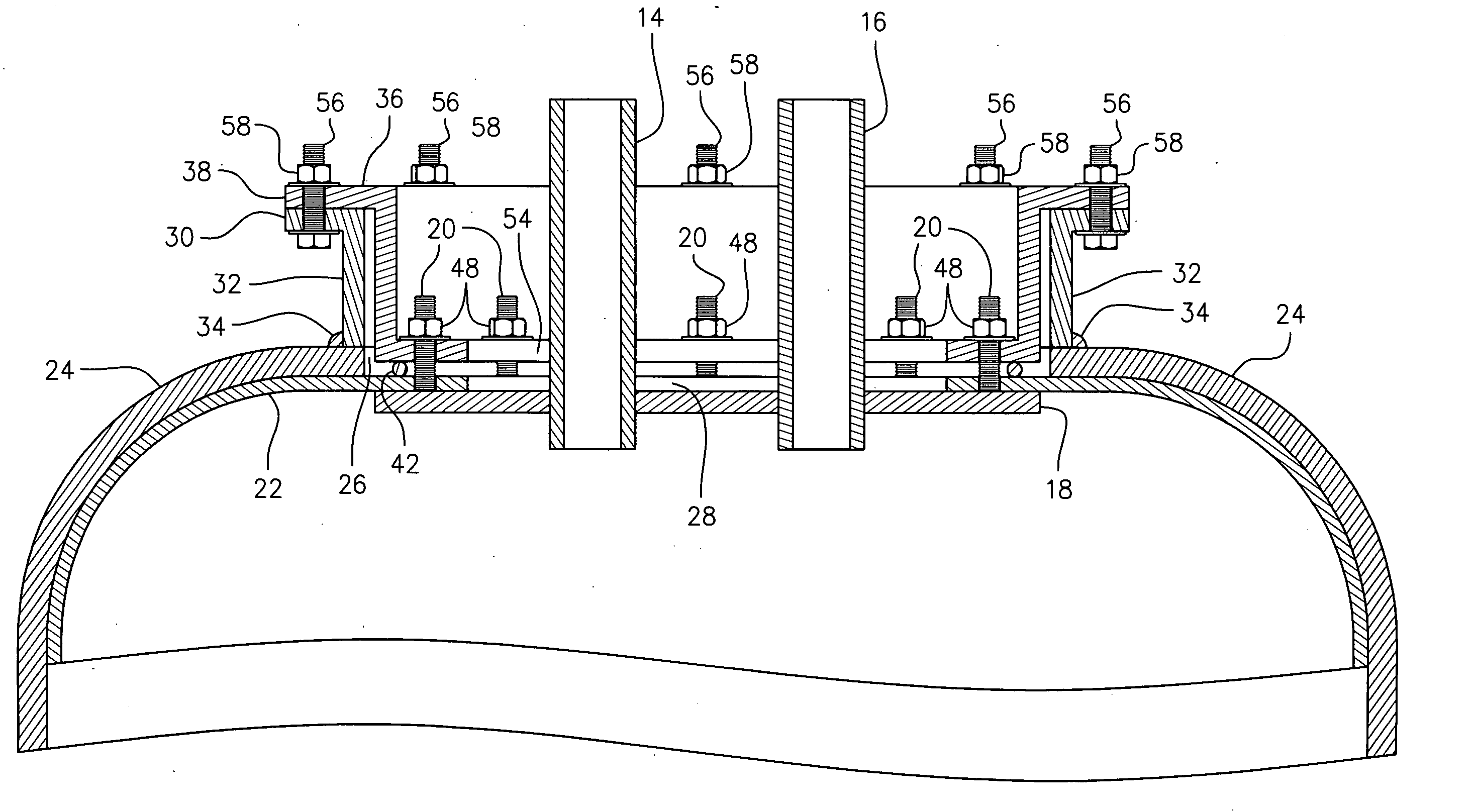
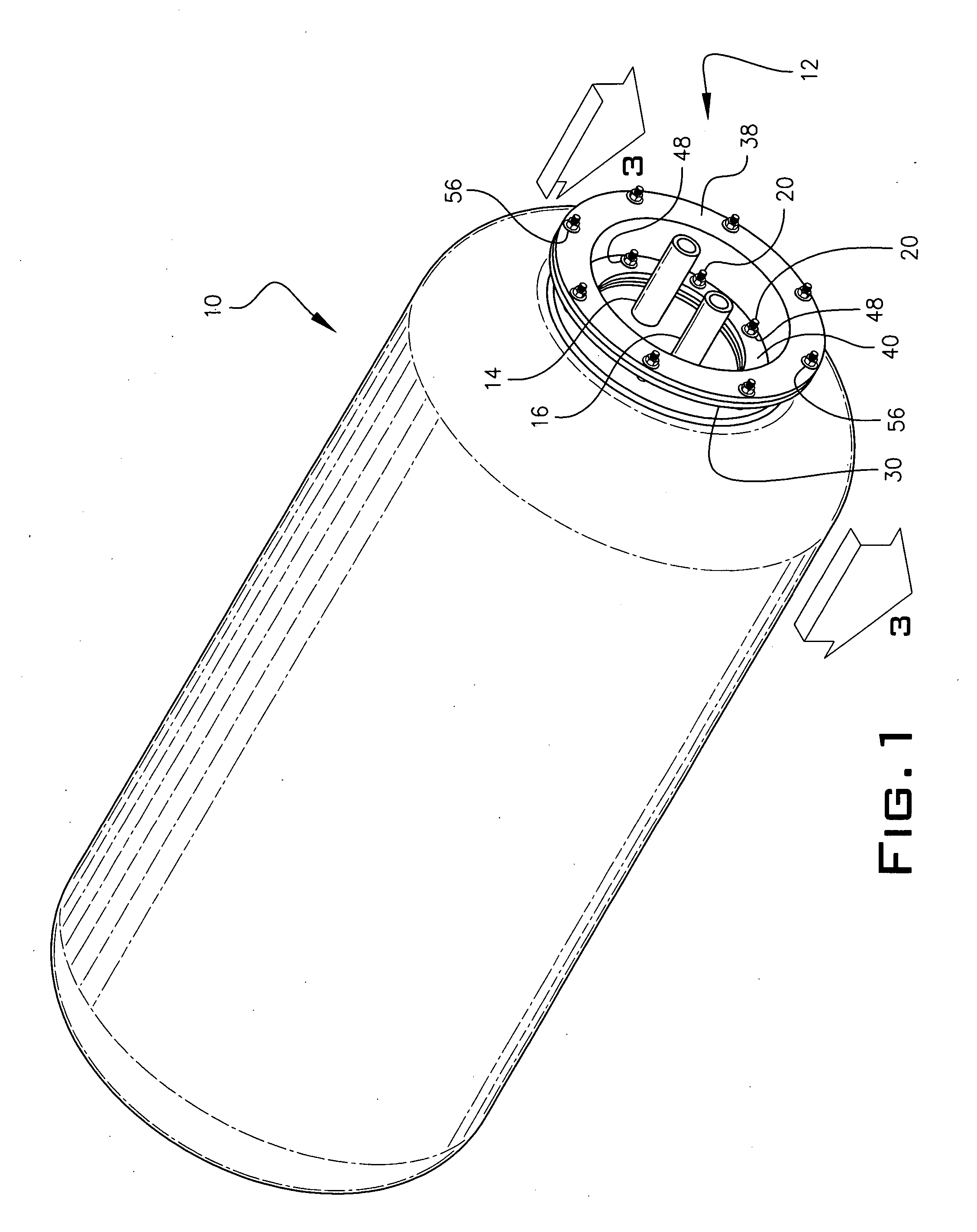
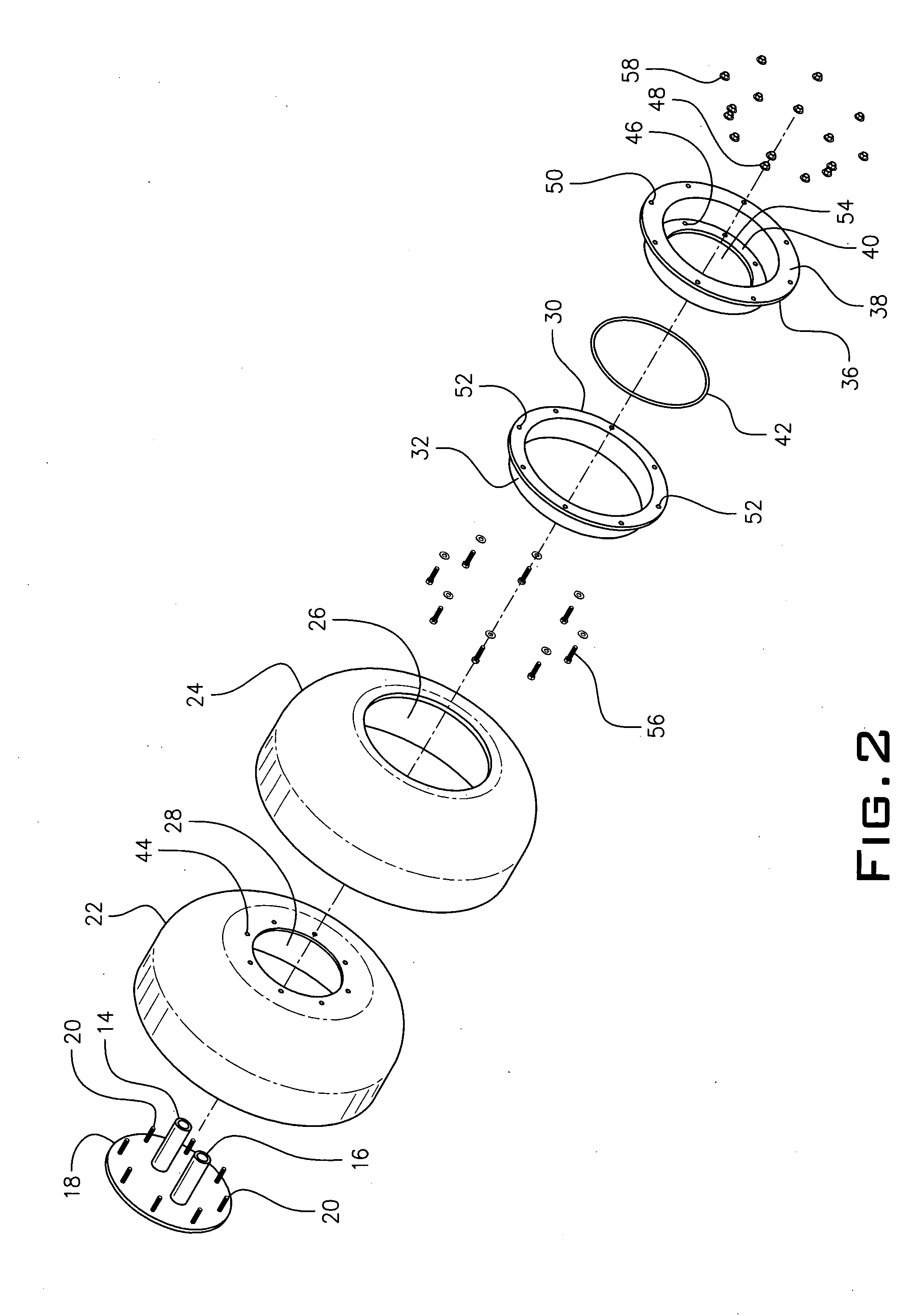
[0013] Referring to FIGS. 1 and 2, the tank 10 has a connection 12 to allow ingress and egress of a liquid to or from the tank through tubes 14 and 16 passing through plate 18 into the interior of the tank 10. Multiple threaded studs 20 project from plate 18. Additional tubes could pass through plate 18, if needed.

[0014] A top portion of liner 22 abuts an inside surface of tank head 24. The liner 22 has a central annular opening 28 that is aligned with, but smaller than, central annular opening 26 in tank head 24. A tank head flange 30 has a collar 32 that is welded 34 adjacent to annular opening 26.

[0015] As seen in FIG. 3, a flange cap 36 has an upper annular flange 38 integral with, but spaced apart from, a lower annular flange 40. An O-ring 42 is located between the lower annular flange 40 and the liner 22. Studs 20 mounted on flange plate 18 pass throug...


PUM


Abstract

The connection employs a plate with at least one through hole for receipt of a liquid conduit tube and at least two projecting threaded studs. A portion of a flexible, non-molded removable liner is mounted between the plate and an inside surface a liquid containing tank having an annular opening. The liquid conduit tube passes through an annular opening in the flexible liner and a flange cap or threaded insert is engaged to either a tank head flange or threaded pipe welded to the tank adjacent to the annular opening. The flange cap or threaded insert receives the studs and nuts are tightened down over the studs tightly pressing the portion of the flexible liner to the inside surface of the tank.

Description

BACKGROUND OF THE INVENTION [0001] This invention relates to connections for a liner in a tank containing liquids. More particularly, it refers to connections to a flexible, non-molded liner mounted within a liquid storage vessel. [0002] In potable hot water tanks, it is necessary to provide a flexible, non-molded liner which is resistant to corrosive attack from salts and other materials in the water. As set forth in U.S. Pat. No. 4,981,112, incorporated herein by reference, the prior art uses a bolt or flange on the water tank exterior at an inlet and outlet port to form a seal with each of corresponding inlet and outlet ports on the liner. Such a flexible, non-molded liner can be replaced by unbolting the bolt or flange on the water tank exterior. However, the connection of a replacement liner is cumbersome and difficult to install. A more easily mountable means of installing a flexible, non-molded liner in a liquid containing tank is needed. SUMMARY OF THE INVENTION [0003] The p...

Claims


Application Information

Patent Timeline
Patent Type & Authority Applications(United States)
IPC IPC(8): B65D6/00F24H1/18
CPCF24H1/183
Inventor WOOLLEN, DONALD E. JR.
Owner AQUA TECH INC
Why Eureka
Try Eureka