Gas spring with a protective sleeve for a rolling bellows

a technology of gas spring and protective sleeve, which is applied in the direction of shock absorbers, semiconductor/solid-state device details, transportation and packaging, etc., can solve the problems of comparatively expensive tubular body and unavoidable dirt exposure of linkages, and achieve the effect of simple design

Inactive Publication Date: 2005-08-18
ZF FRIEDRICHSHAFEN AG
View PDF9 Cites 9 Cited by
  • Summary
  • Abstract
  • Description
  • Claims
  • Application Information

AI Technical Summary

Benefits of technology

[0006] The task of the present invention is to create a gas spring which includes a level sensor but which is nevertheless simple in design.
[0007] The great advantage consists in that a comparatively simple gas spring design can be retained, because, for example, it is possible to eliminate a complicated tubular body such as that used according to the state of the art cited above.
[0008] In an embodiment, the receptacle is designed as a pocket, in which the sensor is mounted. For this purpose, the sleeve can be provided with, for example, a pleat, which can be very easily formed in the sleeve material.
[0009] As a further design elaboration, the pocket in the sleeve can be provided with a cover on the side facing the rolling bellows. The sensor is then well protected in its position between the rolling bellows and the sleeve. The cover prevents the rolling bellows from destroying the sensor and also prevents the rolling bellows from expanding toward the pocket and thus from being subjected to excessive stress.
[0010] It is also possible to provide a protective bellows, which axially adjoins the sleeve, in which case the sensor will be located between the sleeve and the protective bellows. This possibility allows the use of a sleeve with a very simple profile, because the sleeve forms only a part of the receptacle, whereas the protective bellows covers the larger area of the sensor on the outside.

Problems solved by technology

The linkage is unavoidably exposed to dirt from the road and must be adjusted carefully to prevent the level from being set incorrectly.
Because of its asymmetric profile, the tubular body is a comparatively expensive component.

Method used


Image

  • Gas spring with a protective sleeve for a rolling bellows
  • Gas spring with a protective sleeve for a rolling bellows
  • Gas spring with a protective sleeve for a rolling bellows

Examples


Embodiment Construction

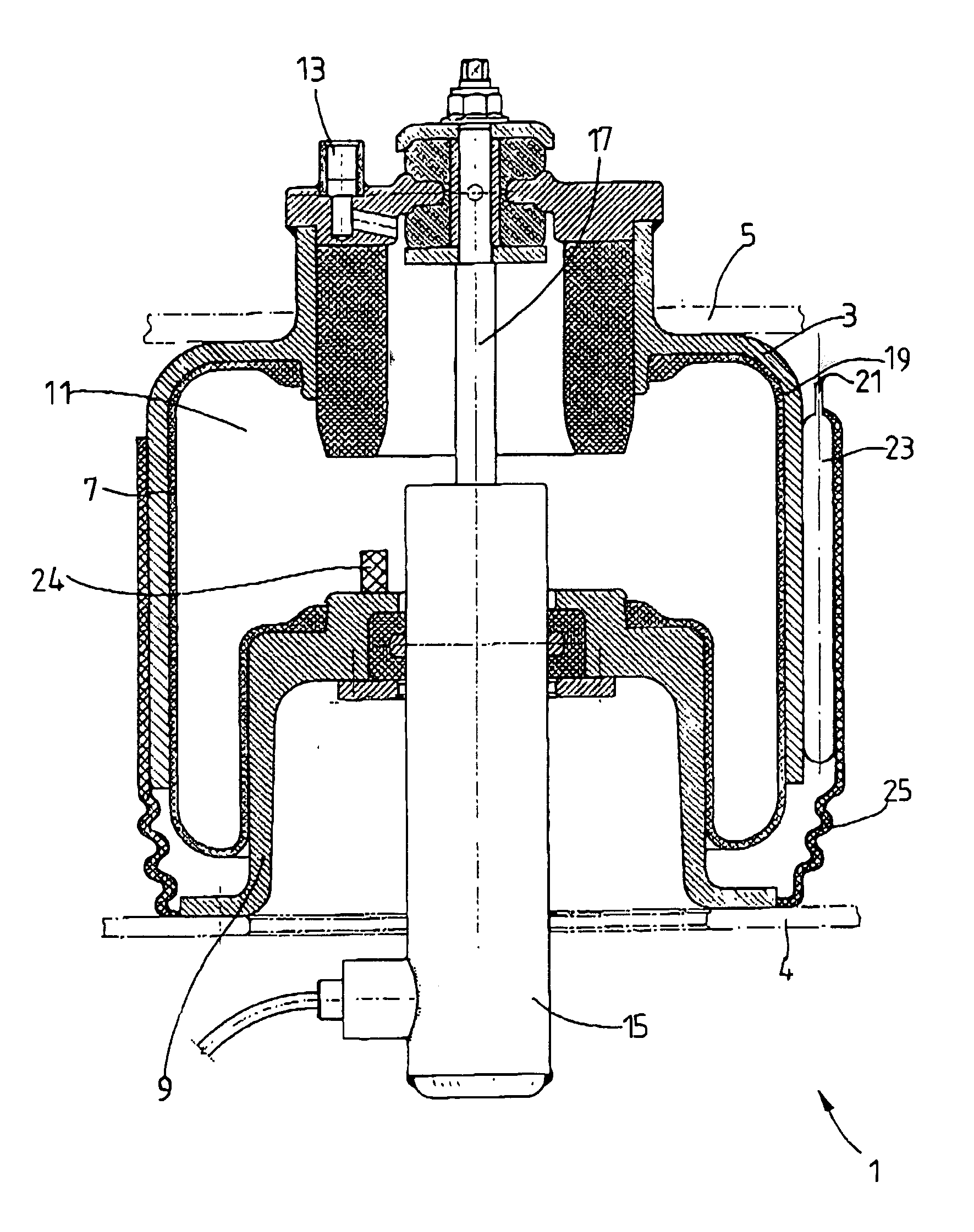
[0020]FIG. 1 shows in simplified form a gas spring 1 of the type which is used, for example, between a vehicle axle 4 and a vehicle body 5. The gas spring 1 has a cover 3, which is mounted permanently on the vehicle body 5. The cover works together with a rolling bellows 7 and a bottom part 9, in this case a rolldown tube, to form a gas-filled spring space 11, the volume of which can be changed at will through a connection 13. A vibration damper 15 of any desired design is mounted coaxially with respect to the gas spring; the piston rod 17 of the vibration damper is also attached permanently to the vehicle body.

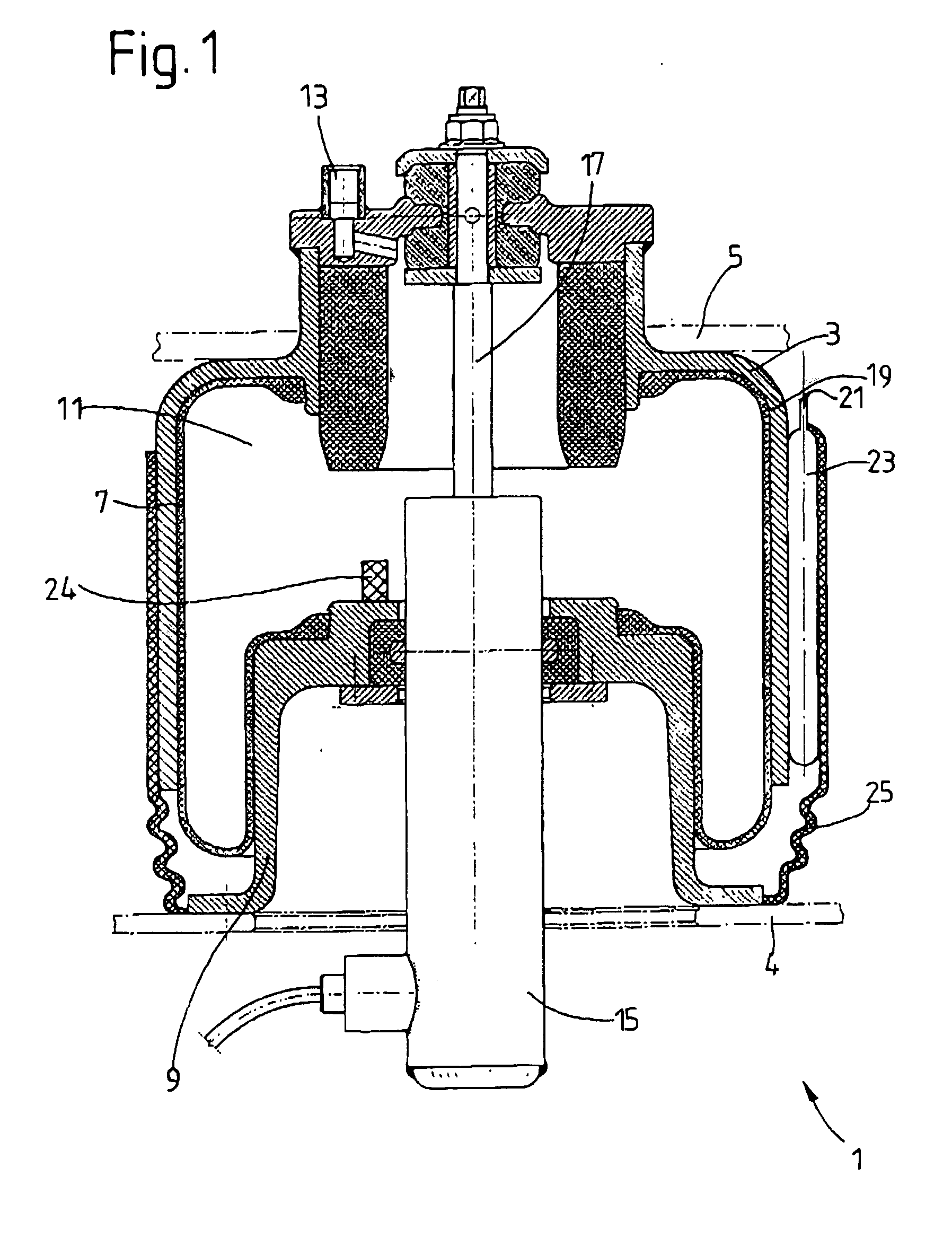
[0021] The rolling bellows 7 should preferably be thin-walled. To protect it against external influences, a sleeve 19 is provided, which is formed as one piece with the cover 3 and covers at least part of the outside surface of the rolling bellows. The sleeve provides a receptacle 21 for a sensor 23, which detects the stroke position of the gas spring. In this embodiment, a ...


PUM


Abstract

Gas spring includes a cover which works together with a rolling bellows and a bottom part to form a gas-filled spring space, where at least part of the outside surface of the rolling bellows is covered by a sleeve. The sleeve provides a receptacle for at least one sensor which detects the stroke position of the gas spring.

Description

BACKGROUND OF THE INVENTION [0001] 1. Field of the Invention [0002] The invention pertains to a gas spring including a bottom part, a cover, a rolling bellows fixed between the bottom part and the cover to form a gas filled spring space, and a sensor for determining the stroke position. [0003] 2. Description of the Related Art [0004] A gas spring in combination with a vibration damper is known from ATZ 2002, Special Edition Audi A8, p. 86 ff. The gas spring comprises a cover, which is attached to the vehicle body and which is connected to the top end of a rolling bellows. A bottom end of the bellows is clamped to a rolldown tube. As can be derived from the report, a comparatively thin-walled bellows is used to minimize the stiffening of the gas spring under high-frequency excitation, A thin-walled bellows, however, is more sensitive to impacts by stones, so that a protective metal sleeve is used, which is also connected to the cover of the gas spring. The gas spring is part of a lev...

Claims


Application Information

Patent Timeline
Patent Type & Authority Applications(United States)
IPC IPC(8): B60G11/27B60G15/12B60G17/00B60G17/019B60G17/052F16F9/05F16F9/32
CPCB60G11/27B60G17/01933B60G17/0521F16F9/3292B60G2204/201B60G2400/252F16F9/05B60G2204/111F16F9/38H01L23/5388H01L23/28H01L23/66
Inventor THOMAE, ACHIMPRADEL, ROBERT
Owner ZF FRIEDRICHSHAFEN AG
Why Eureka
Try Eureka