Dimming circuit for a gas-discharge lamp

Inactive Publication Date: 2005-08-18
CHUAN SHIH INDAL
View PDF4 Cites 4 Cited by
  • Summary
  • Abstract
  • Description
  • Claims
  • Application Information

AI Technical Summary

Benefits of technology

[0006] It is another object of the present invention to provide a dimming circuit of a gas-discharge lamp, which prevents burning out of the gas-discharging lamp when regulating the light intensity of the gas-discharge lamp.
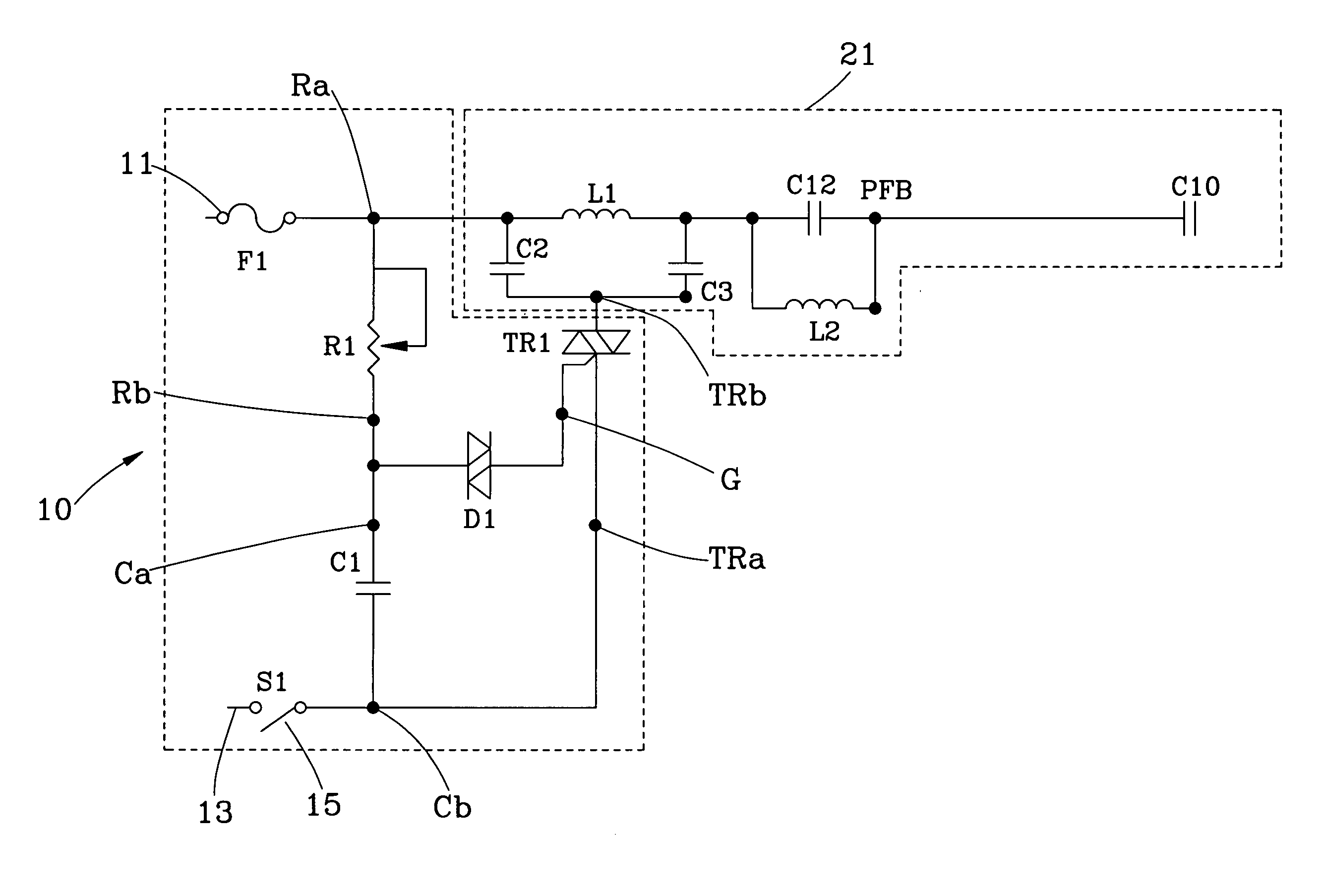
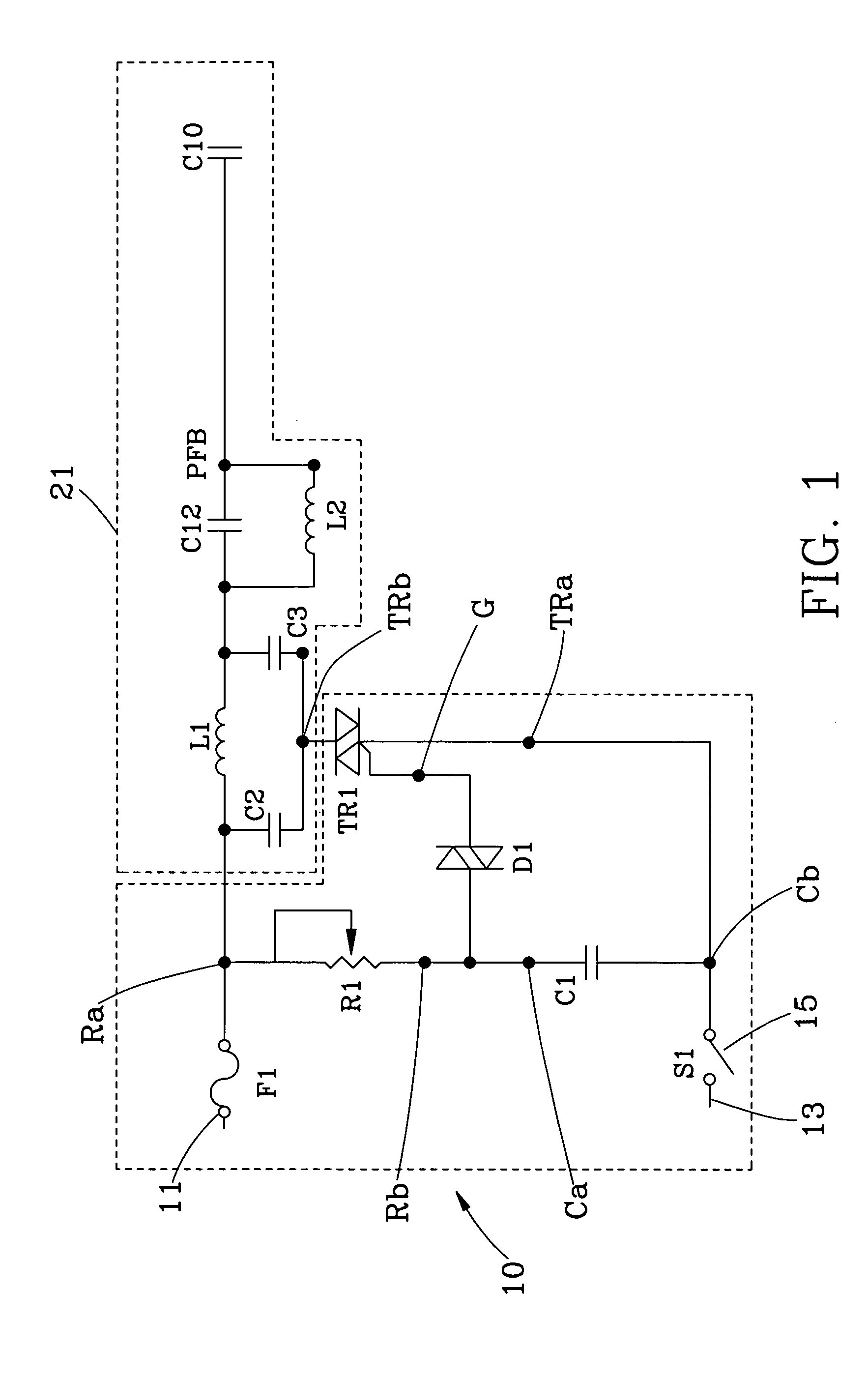
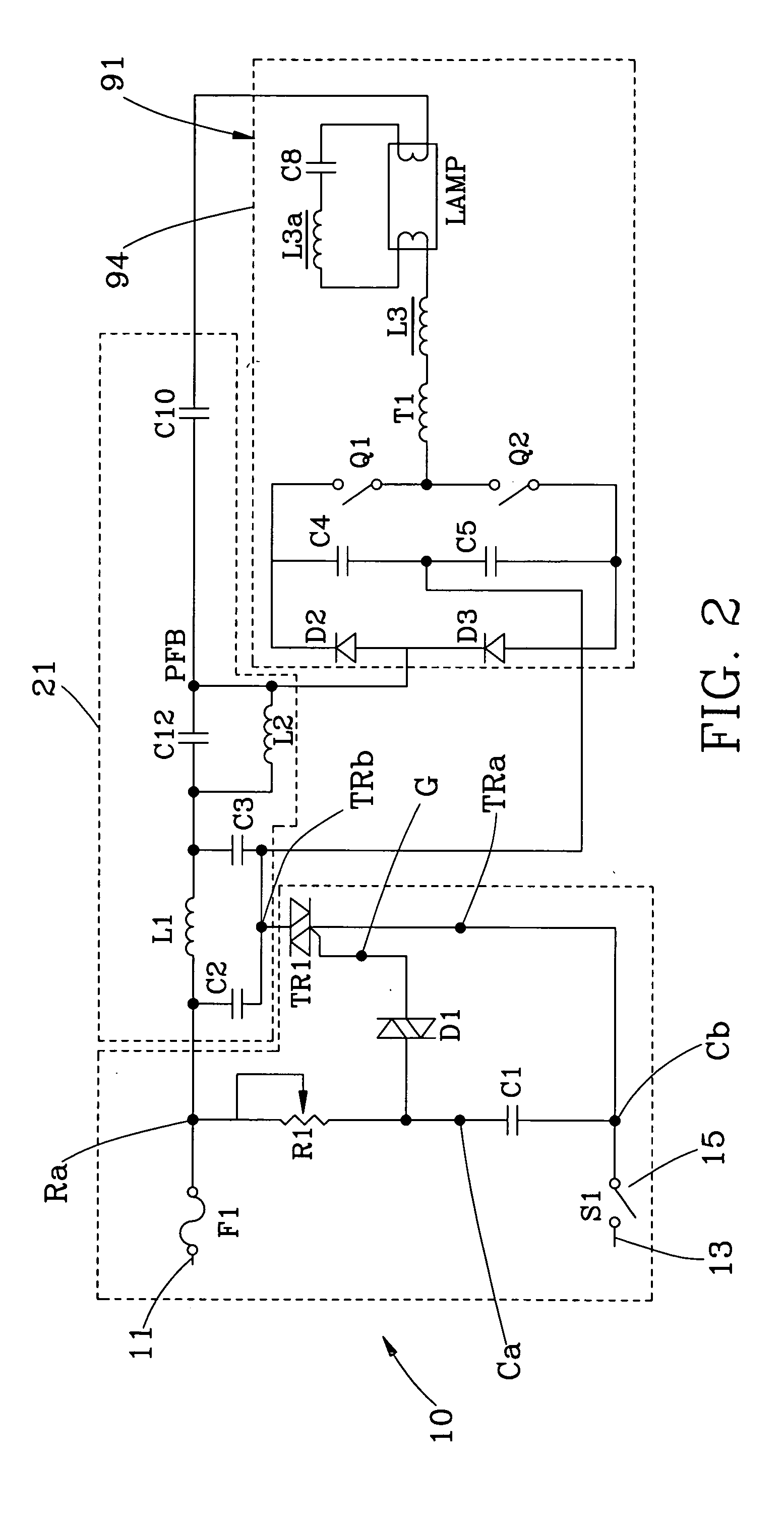
[0007] The dimming circuit of a gas-discharge lamp comprises a first terminal and a second terminal for inputting AC power; a variable resistor, the variable resistor having a second end connected to the first input terminal; a capacitor, the capacitor having a first end connected to the first end of the variable resistor and a second end connected to the second input terminal; a DIAC diode, the DIAC diode having a first end connected to the first end of the variable resistor and the first end of the capacitor, and a second end; a TRIAC, the TRIAC having the gate thereof connected to the second end of the bi-directional diode, a first end connected to the second input terminal, and a second end; and a switch connected to one of the first input terminal and the second input terminal for circuit on / off control, for enabling the light intensity of the gas-discharge lamp to be regulated subject to change of the resistance value of the variable resistor.

Problems solved by technology

However, this dimmer is not suitable for use to regulate the light intensity of a gas-discharge lamp (power-saving lamp bulb, fluorescent lamp tube) because the gas-discharge lamp is unstable and may burn out during low output, and the gas-discharge lamp may burn out when regulating the light intensity at this time.
Therefore, few light regulation circuits or devices are seen in the market.

Method used


Image

  • Dimming circuit for a gas-discharge lamp
  • Dimming circuit for a gas-discharge lamp
  • Dimming circuit for a gas-discharge lamp

Examples


Embodiment Construction

[0010] Referring to FIG. 1, a light regulating circuit 10 in accordance with the present invention is shown comprising a first input terminal and a second input terminal 11, 13, a variable resistor R1, a capacitor C1, a DIAC diode D1, a TRIAC TR1, and a switch 15.

[0011] The first and second input terminals 11, 13 are connected to city power supply for inputting AC power.

[0012] The variable resistor R1 has a first end Ra connected to the capacitor C1, and a second end Rb connected to the first input terminal 11. The variable capacitor C1 has a first end Ca connected to the first end Ra of the variable resistor R1, and a second end C2 connected to the second input terminal 12.

[0013] The DIAC diode D1 has one end connected to the first end Ra of the variable resistor R1 and the first end Ca of the variable capacitor C.

[0014] The TRIAC TR1 has the gate connected to the other end of the bi-directional diode D1, and the first end TRa connected to the second input terminal 13.

[0015] T...


PUM


Abstract

A dimming circuit for a gas-discharge lamp includes a first terminal and a second terminal for inputting AC power, a variable resistor and a capacitor connected with the respective first end to each other and the respective second end to the first input terminal and the second input terminal respectively, a bi-directional diode connected with one end to the first end of the variable resistor and the first end of the capacitor, a TRIAC, which has the gate thereof connected to the second end of the bi-directional diode and one end connected to the second input terminal, and a switch connected in series between the second input terminal and the capacitor for circuit on / off control, for enabling the light intensity of the gas-discharge lamp to be regulated subject to change of the resistance value of the variable resistor.

Description

BACKGROUND OF THE INVENTION [0001] 1. Field of the Invention [0002] The present invention relates to a gas-discharge lamp and more specifically, to a dimming circuit for controlling the light intensity of a gas-discharge lamp. [0003] 2. Description of the Related Art [0004] Conventionally, the adjustment of the light intensity of a lamp, for example, incandescent lamp or halogen lamp, is made directly through a dimmer. The dimmer regulates the light intensity of the lamp by controlling the current passing to the lamp bulb. However, this dimmer is not suitable for use to regulate the light intensity of a gas-discharge lamp (power-saving lamp bulb, fluorescent lamp tube) because the gas-discharge lamp is unstable and may burn out during low output, and the gas-discharge lamp may burn out when regulating the light intensity at this time. Therefore, few light regulation circuits or devices are seen in the market. SUMMARY OF THE INVENTION [0005] The present invention has been accomplishe...

Claims


Application Information

Patent Timeline
IPC IPC(8): H05B41/392
CPCY10S315/04H05B41/3924
Inventor WANG, CHING-NAN
Owner CHUAN SHIH INDAL
Why Eureka
Try Eureka