Viewing angle adjustment system for a monitor

a technology for viewing angle and adjustment system, which is applied in the direction of instruments, curtain suspension devices, electrical apparatus casings/cabinets/drawers, etc., can solve the problems of inconvenient viewing angle adjustment and the inability of the viewer to view the monitor

Inactive Publication Date: 2005-08-18
CLO SYST
View PDF27 Cites 105 Cited by
  • Summary
  • Abstract
  • Description
  • Claims
  • Application Information

AI Technical Summary

Benefits of technology

[0006] This invention provides a support arm to couple a monitor to a surface such as a wall or ceiling to remotely or automatically adjust the viewing angle of the monitor. The support arm includes at least one motor along a pivot axis in the support arm. The motor may be activated by a processor based on the control signal provided by the remote control. The support arm may include a plurality of pivot axes with a motor in each of the pivot axis to adjust the viewing angle along at least one plane such as the vertical and / or horizontal plane. The support arm may be also provided with a tracking device that follows the movement of the viewer to adjust the viewing angle of the monitor corresponding to the movement of the viewer. The support arm may also receive periodic signal from the remote control to determine the location of the remote control. Based on the periodic signal, the processor may adjust the viewing angle of the monitor towards the location of the remote control.

Problems solved by technology

As the viewer moves from one area to another area, such as from the family room to the kitchen, the viewer may not be able to view the monitor.
In addition, in situations where the monitor is mounted in a remote location or high above the floor, it may be inconvenient for the viewer to adjust the viewing angle of the monitor.

Method used


Image

  • Viewing angle adjustment system for a monitor
  • Viewing angle adjustment system for a monitor
  • Viewing angle adjustment system for a monitor

Examples


Embodiment Construction

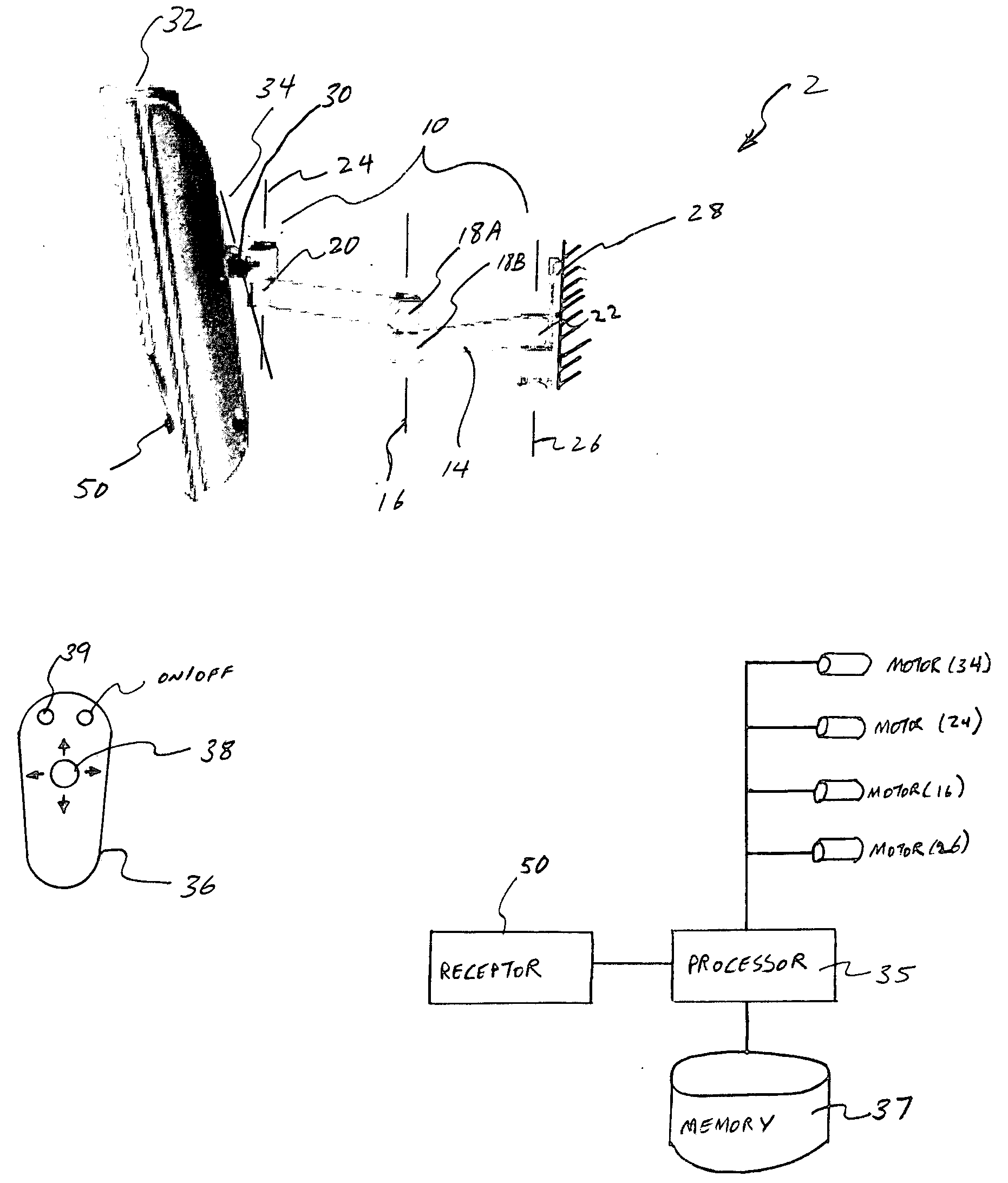
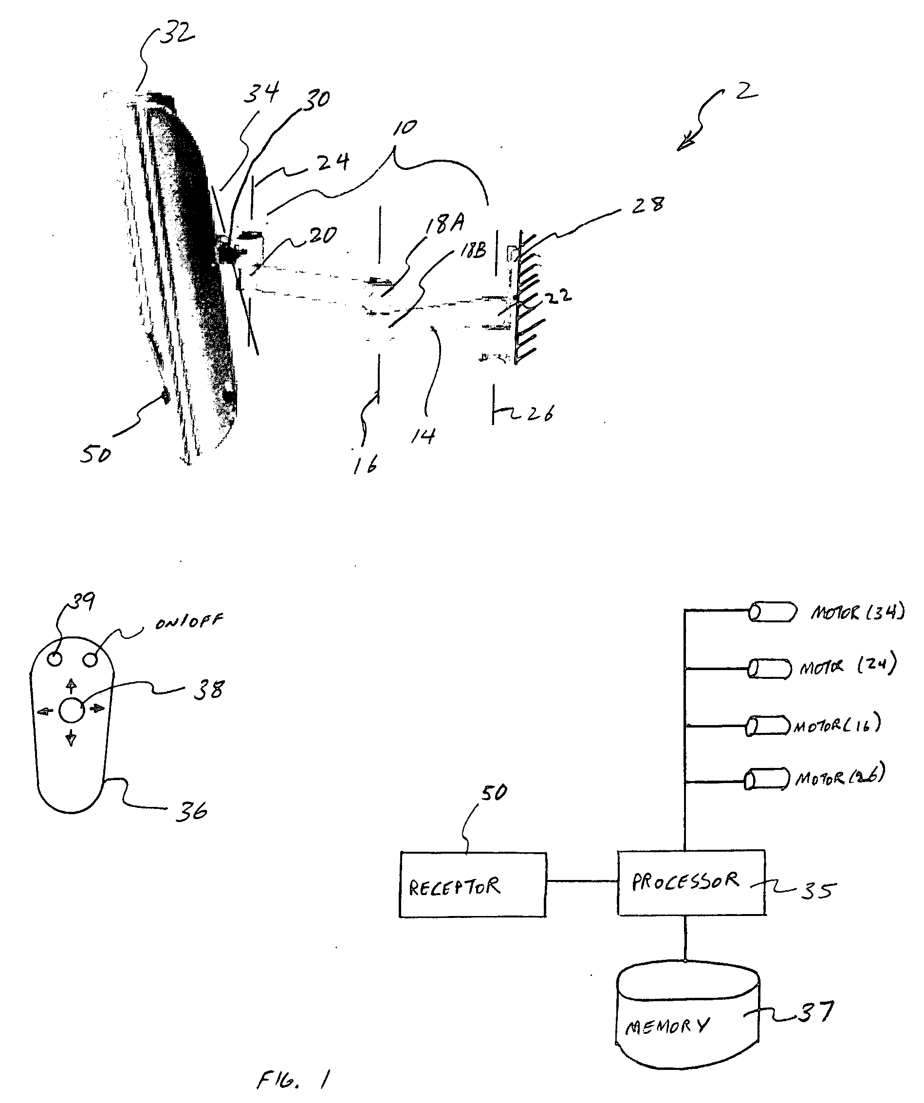
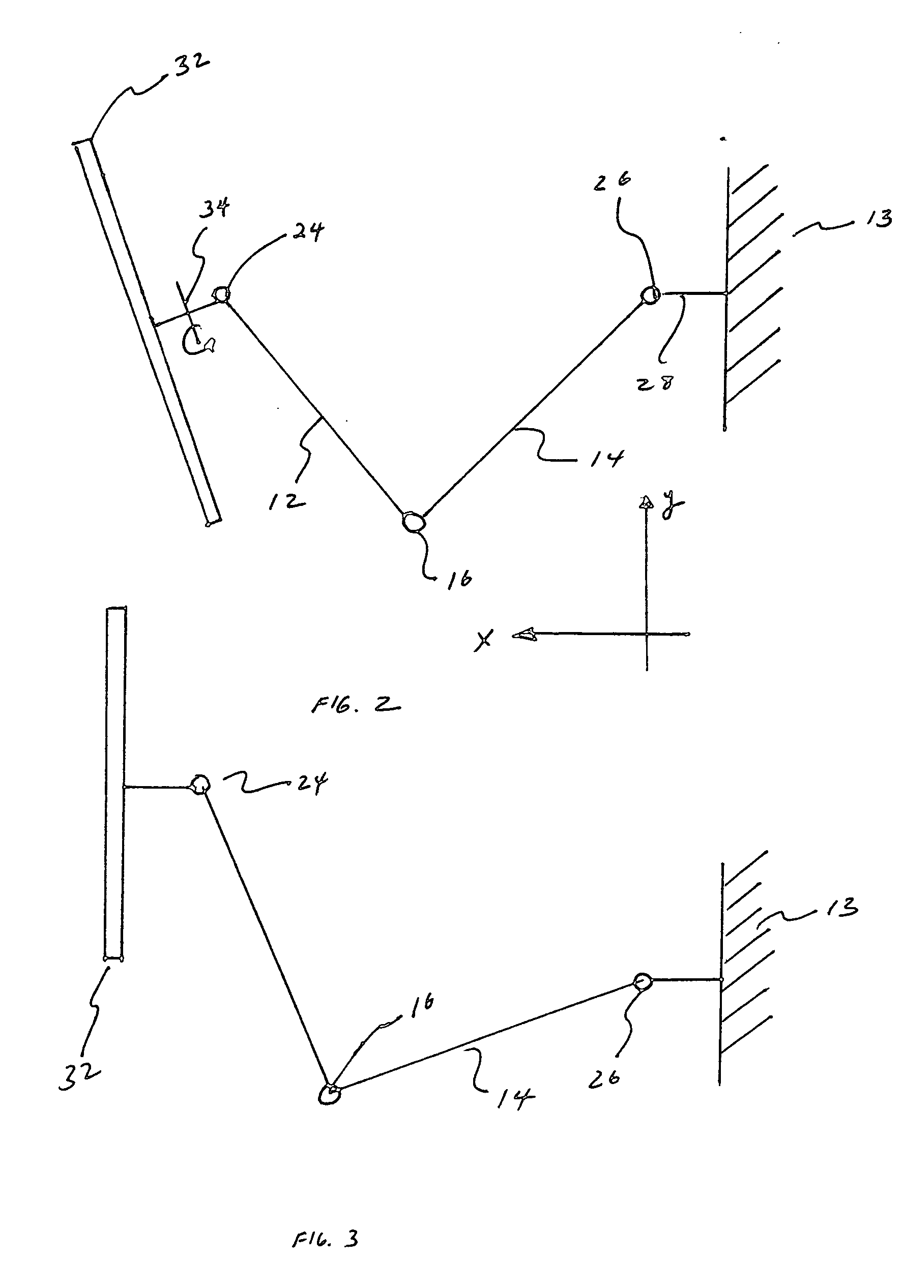
[0020] This invention is generally directed to remotely controlling the viewing angle of the monitor that is mounted onto a surface or in a remote area. FIG. 1 shows a viewing angle adjustment system 2 including a support arm 10 having a plurality of channels 12 and 14. The two channels 12 and 14 may be coupled along the pivot axis 16. Along the pivot axis 16, the two channels 12 and 14 may form a housing 18A and 18B, respectively, adapted to house an electric motor. The electric motor may be a servo motor capable of pivoting or rotating the housing 18A relative to the housing 18B, thereby actuating the channel 12 relative to the channel 14. A variety of different types of motors known to one skilled in the art may be used in the pivot axis. In addition, on the opposite end of the housing 18A, the channel 12 may have a housing 20 adapted to pivotally couple an adaptor 30 about the pivot axis 24. Along the pivot axis 24, the adaptor 30 and the housing 20 may enclose another electric ...


PUM


Abstract

This invention provides a support arm to couple a monitor to a surface such as a wall or ceiling to remotely adjust the viewing angle of the monitor. The support arm includes at least one motor along a pivot axis in the support arm. The motor may be activated by a processor based on the control signal provided by the remote control. The support arm may include a plurality of pivot axes with a motor in each of the pivot axis to adjust the viewing angle along the vertical and horizontal planes. The support arm may be also provided with a tracking device that follows the movement of the viewer to adjust the viewing angle of the monitor corresponding to the movement of the viewer. The support arm may also receive periodic signal from the remote control to determine the location of the remote control. Based on the periodic signal, the processor may adjust the viewing angle of the monitor towards the location of the remote control.

Description

RELATED APPLICATION [0001] This application claims priority to a U.S. provisional patent application Ser. No. 60 / 533,923, entitled SYSTEM FOR REMOTELY ADJUSTING THE VIEWING ANGLE OF A MONITOR, filed Jan. 2, 2004, which is hereby incorporated by reference.BACKGROUND OF THE INVENTION [0002] 1. Field of the Invention [0003] This invention is directed to a support arm capable of adjusting the viewing angle of a monitor remotely and / or automatically to allow a viewer to watch the monitor more comfortably at the desired viewing angle. [0004] 2. General Background [0005] Flat screen monitors such as computer monitors and plasma televisions (collectively referred to as “monitor(s)”) are becoming popular because they can be mounted onto a wall to save floor space and for their aesthetically pleasing appearance. In particular, monitors are generally mounted to a wall with a mechanical support arm then fixed in a desired orientation to maximize the viewing angle of the monitor. To later adjust...

Claims


Application Information

Patent Timeline
Patent Type & Authority Applications(United States)
IPC IPC(8): G09G5/00
CPCF16M11/08F16M11/10F16M11/18Y10S248/919F16M13/027G06F1/1601G06F2200/1612F16M11/2014F16M11/2092
Inventor OH, SUNG I.
Owner CLO SYST
Why Eureka
Try Eureka