
Generating and validating pixel coordinates of a touch screen display

Active Publication Date: 2005-08-18
TRANE INT INC
View PDF13 Cites 22 Cited by
  • Summary
  • Abstract
  • Description
  • Claims
  • Application Information

AI Technical Summary

Benefits of technology

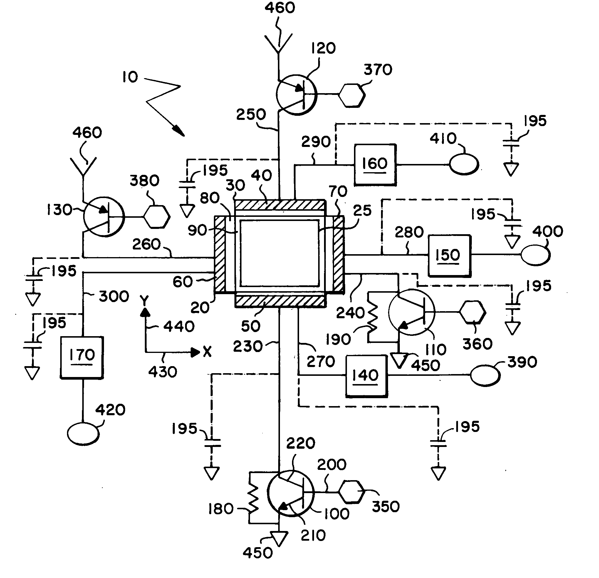
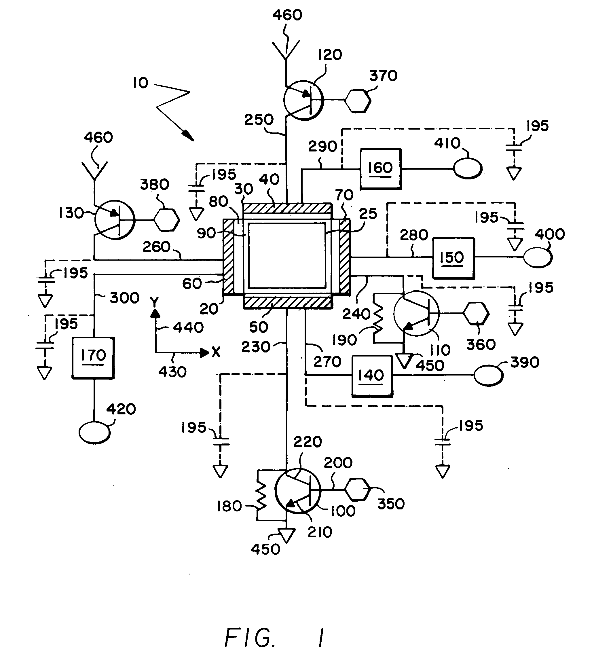
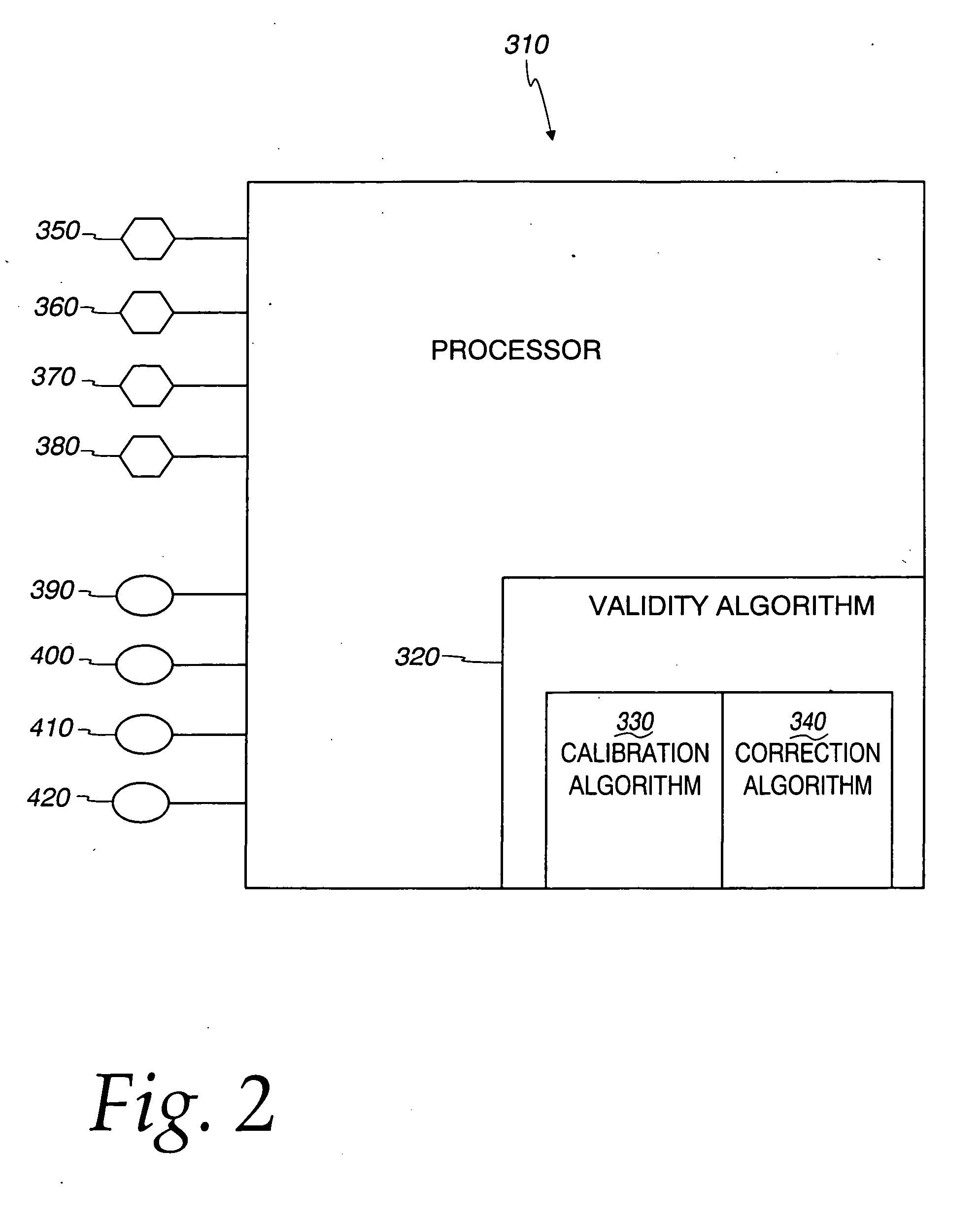
[0010] Apparatus for calibrating the touch-screen display system is provided. “Calibrating” means determining and correcting errors in the estimated coordinates, so the measured coordinates are accurate. This apparatus includes a processor that uses the digital signals it receives from the touch-screen to produce calibrated pixel coordinate estimates. This calibration is performed during real-time generation of the pixel coordinate estimates without the need for any extraordinary input by a user of the system. In other words, the calibrated estimates are produced essentially at the same time the coordinate estimates are produced, so the system automatically recalibrates itself as it is used. Automatic calibration reduces or eliminates the need for manual recalibration.
[0011] Another aspect of the disclosed embodiment is an apparatus for generating and processing multiple calibrated pixel coordinate estimates at a pre-defined sampling rate to determine valid pixel position in order to minimize sampling delays due to settling times. The x-axis position is validated before the system attempts to generate a y-axis position so as not to waste time generating y-axis estimates when x-axis estimates are not valid. Shunts are designed in conjunction with the pre-defined sampling rate to establish pre-determined settling times (corresponding to discharge rates of capacitance on the analog interfaces) such that voltage levels of the analog interfaces can be sampled and processed by the system to indicate a “no touch” state of the system.
[0013] Another aspect of the disclosed embodiment is a method for generating and processing multiple calibrated pixel coordinate estimates at a pre-defined sampling rate to determine valid pixel position in order to minimize sampling delays due to settling times. The x-axis position is validated before the system attempts to generate a y-axis position so as not to waste time generating y-axis estimates when x-axis estimates are not valid. Noisy estimates are inherently reduced in the touch-screen display system employing unique shunting techniques in conjunction with driving techniques in the system. These shunting techniques are used in conjunction with a pre-defined sampling rate to establish pre-determined settling times (corresponding to discharge rates of capacitance on the analog interfaces) such that voltage levels on these analog interfaces can be sampled and processed by the system to indicate a “no touch” state of the system.
[0014] By using the foregoing techniques, an approach to generating pixel coordinate estimates that minimizes sampling delays, reduces corruption of estimates due to noise, enhances ESD protection, and eliminates the need for user-interactive calibration is achieved.

Problems solved by technology

If the samples are corrupted by noise or by drift of some parameter of the system, then these samples yield an incorrect indication of where the user has touched the display screen.
Also, in many touch-screen display systems, only an active touch of the display screen (or apparent touch caused by system noise) is detected.

Method used


Image

  • Generating and validating pixel coordinates of a touch screen display
  • Generating and validating pixel coordinates of a touch screen display
  • Generating and validating pixel coordinates of a touch screen display

Examples


Embodiment Construction

[0032] The features of one embodiment enable improved efficiency in generating pixel coordinate estimates through enhanced techniques of calibration and validation of the estimates. As used in this specification and claims, a pixel coordinate estimate corresponds to that pixel position on the touch-screen display that is an estimate of where a user has touched the screen. This embodiment offers a more efficient approach to generating pixel coordinate estimates that minimizes delays, reduces corruption of estimates due to noise, enhances ESD protection, and eliminates the need for user-interactive calibration. The pixel coordinate estimates are characterized as digital signal values in a processor of the touch-screen display system. These digital signal values are generated, in part, from a set of analog voltage levels, sampled from analog resistive screens in the touch-screen display system, corresponding to the position of where a user has touched the display screen.

[0033]FIG. 1 i...


PUM


Abstract

An enhanced touch-screen display system is disclosed for generating pixel coordinate estimates corresponding to a location on a display screen touched by a user. The system is an analog resistive touch-screen display system having a processor and associated software algorithms to allow for the calibration and validation of pixel coordinate estimates as an integral part of the real-time generation of the pixel coordinate estimates. Multiple calibrated pixel coordinate estimates are generated and processed at a pre-defined sampling rate to determine a valid pixel position to minimize sampling delays due to settling times. The x-axis position is also validated before the system attempts to generate a y-axis position to avoid the wasted time for generating y-axis estimates when x-axis estimates are corrupted. Noisy estimates are inherently reduced in the touch-screen display system by providing shunts across certain drivers in the system that also allow for detection of a “no touch” state.

Description

BACKGROUND OF THE INVENTION [0001] This disclosed embodiment relates to a touch-screen display system for generating pixel coordinate estimates responsive to a user touching (pressing a key on) a display screen, and more particularly relates to improving the efficiency of generating such pixel coordinate estimates through enhanced techniques of calibration and validation of the estimates. [0002] In a typical touch-screen display system, an x-axis coordinate position is sampled and then a y-axis coordinate position is sampled to indicate a pixel location where a user has touched the display screen. If the samples are corrupted by noise or by drift of some parameter of the system, then these samples yield an incorrect indication of where the user has touched the display screen. [0003] Typically, the system is controlled to insert timing delays into the sampling process to allow the various x-axis and y-axis drivers to settle out as they are switched back and forth between x and y so n...

Claims


Application Information

Patent Timeline
IPC IPC(8): G06F3/041G09G5/00
CPCG06F3/0418G06F3/04186
Inventor DEGROOT, JEFFREY J.KRAJEWSKI, THOMAS G.
Owner TRANE INT INC
Learn More