Aspheric diffractive reference for interferometric lens metrology

a technology of interferometric lens and reference surface, which is applied in the direction of geometric properties/aberration measurement, structural/machine measurement, instruments, etc., can solve the problems of difficult to create an ideal reference surface of more complicated surfaces with which to compare manufactured surfaces, and the number of complicated reference surfaces required to measure a wide range of complicated surfaces is impractical

Inactive Publication Date: 2005-08-18
DIGITALOPTICS CORPORATION
View PDF5 Cites 42 Cited by
  • Summary
  • Abstract
  • Description
  • Claims
  • Application Information

AI Technical Summary

Benefits of technology

[0005] It is a feature of the present invention to provide a diffractive reference at different locations throughout an interferometer used to measure an optical surface. It is another feature of the present invention to shape the wavefront to match an ideal surface of the lens under test. It is yet another feature of the present invention to provide a diffractive reference without altering the interferometer.

Problems solved by technology

Physical measurement of a surface, such as using a profilometer, is very time consuming.
While interferometry allows straightforward testing of simple surfaces, such as flat surfaces and spherical surfaces, creating an ideal reference of more complicated surfaces with which to compare the manufactured surface is difficult.
Further, the number of complicated reference surfaces required to measure a wide range of complicated surfaces is impractical.
Accurate interferometric metrology of aspheric surfaces continues to be complicated by several factors.
These include decentration, tilt and aperture error between the optical probe wavefront and the surface under test.
Even for a theoretical surface where the boundary and center are well defined and there are no coma, astigmatism or tilt aberrations, the radius of curvature (Rc) of the asphere cannot be accurately resolved.
However, these techniques still involve validation of many complicated reference surfaces.

Method used


Image

  • Aspheric diffractive reference for interferometric lens metrology
  • Aspheric diffractive reference for interferometric lens metrology
  • Aspheric diffractive reference for interferometric lens metrology

Examples


Embodiment Construction

[0014] The present invention will be described in detail through embodiments with reference to accompanying drawings. However, the present invention is not limited to the following embodiments but may be implemented in various types. The embodiments are only provided to make the disclosure of the invention complete and make one having an ordinary skill in the art know the scope of the invention. Throughout the drawings, the same reference numerals denote the same elements.

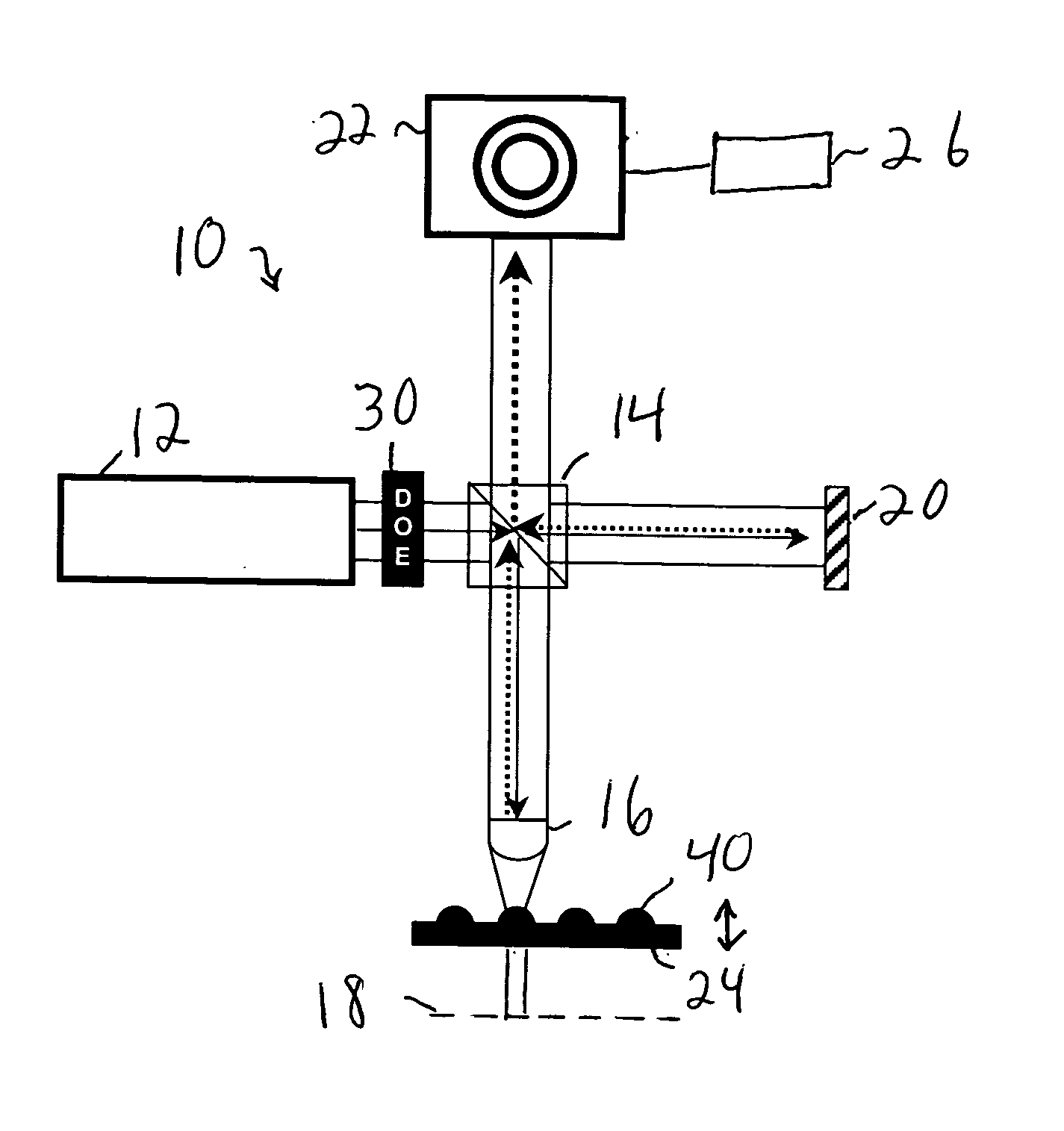
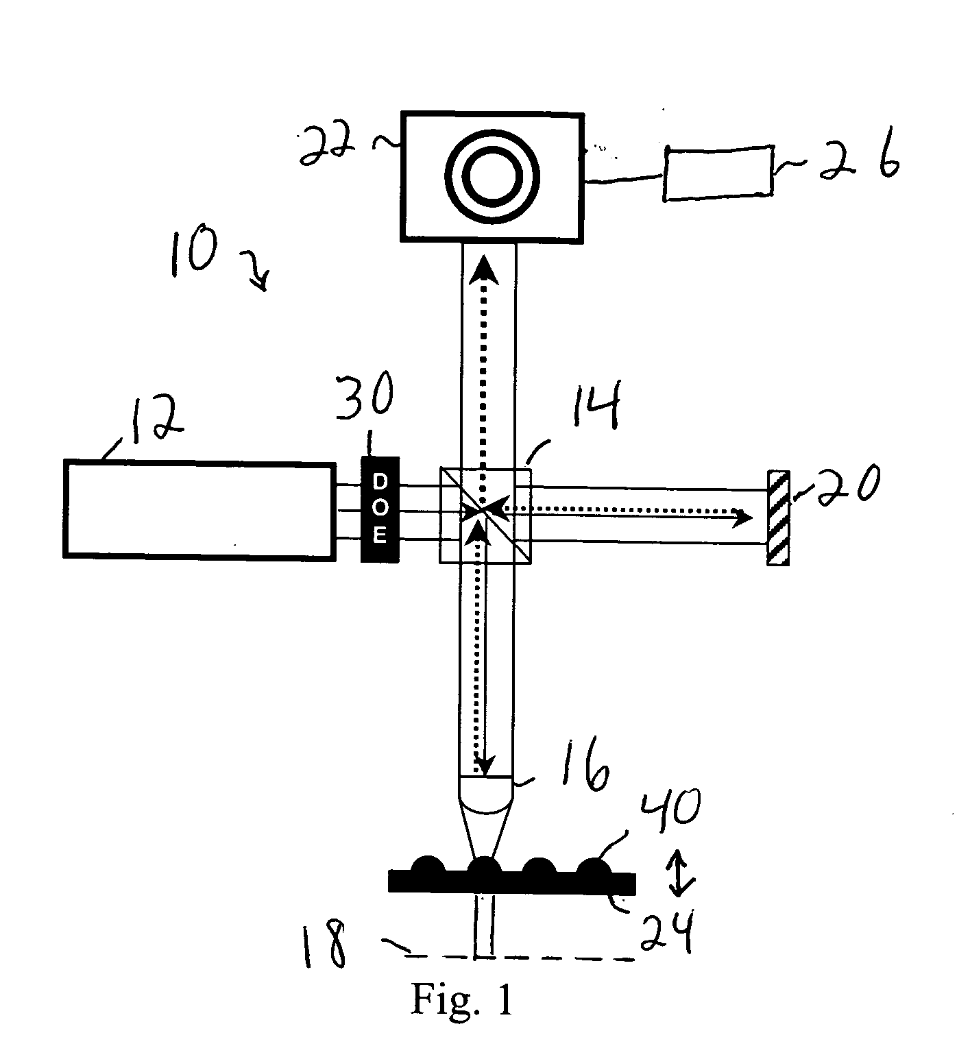
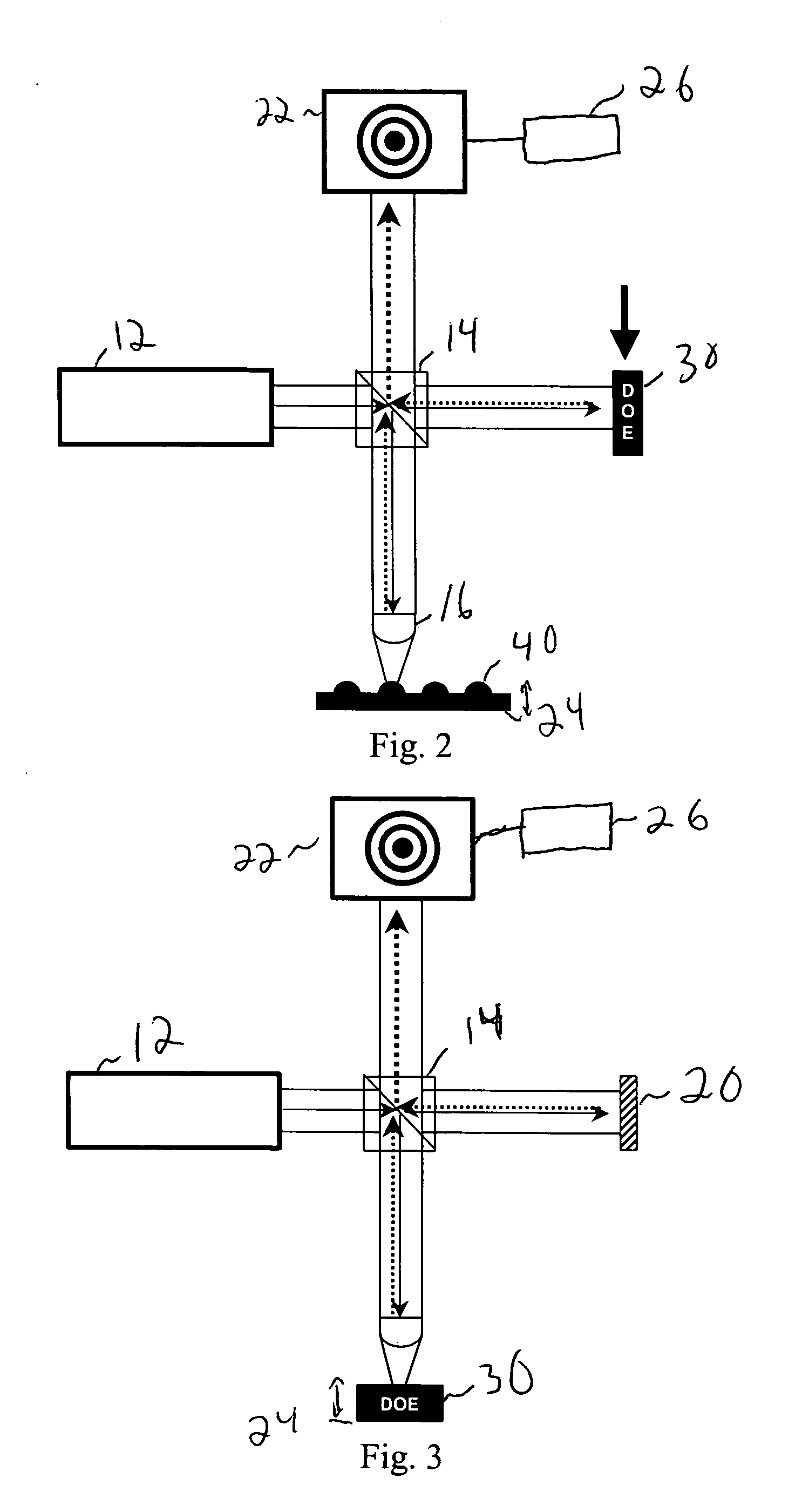
[0015] A diffractive optic may be used to generate an accurate aspheric reference. Since validation of the diffracted wavefront can be accomplished by measurement of flat steps, i.e., the surface is discontinuous in z, the integrity of the diffracted wavefront can be established by a more conventional testing of the mechanical surface structure. Further, the diffractive optic may be used with a variety of aspheres. The diffractive optic may be placed in numerous locations in the interferometer, as illustrated belo...


PUM


Abstract

A diffractive optical element is used to provide an aspherical wavefront to a lens under test in an interferometer or to provide an aspheric null surface. When providing an aspherical wavefront, the diffractive may be in the path of one or both beams to be interfered. Robust and adaptable aspheric testing may be realized.

Description

BACKGROUND [0001] The accuracy to which a refractive optical element can be manufactured is fundamentally determined by how precisely the shape of the surface of the optical element can be measured. Physical measurement of a surface, such as using a profilometer, is very time consuming. Interferometry is used to measure the departure of a manufactured optical surface from an ideal optical surface. While interferometry allows straightforward testing of simple surfaces, such as flat surfaces and spherical surfaces, creating an ideal reference of more complicated surfaces with which to compare the manufactured surface is difficult. Further, the number of complicated reference surfaces required to measure a wide range of complicated surfaces is impractical. [0002] Accurate interferometric metrology of aspheric surfaces continues to be complicated by several factors. These include decentration, tilt and aperture error between the optical probe wavefront and the surface under test. All of...

Claims


Application Information

Patent Timeline
Patent Type & Authority Applications(United States)
IPC IPC(8): G01B9/02G01M11/02G02B27/09
CPCG01M11/0242G01M11/0271G01B9/02018G01B9/02039G01B9/02024G02B27/0944
Inventor BOOMGARDEN, MARK D.WELCH, WILLIAM HUDSONLINNEN, CHRISTOPHER J.
Owner DIGITALOPTICS CORPORATION
Why Eureka
Try Eureka