Latch structure

Active Publication Date: 2005-08-18
ASUSTEK COMPUTER INC
View PDF9 Cites 23 Cited by
  • Summary
  • Abstract
  • Description
  • Claims
  • Application Information

AI Technical Summary

Benefits of technology

[0014] As described before, in the latch structure of the invention, the button is adjacent to the hook unit. In c

Problems solved by technology

However, the design of the conventional notebook will increase the fabricatin

Method used


Image

  • Latch structure
  • Latch structure
  • Latch structure

Examples


Embodiment Construction

[0024] The present invention will be apparent from the following detailed description, which proceeds with reference to the accompanying drawings, wherein the same references relate to the same elements.

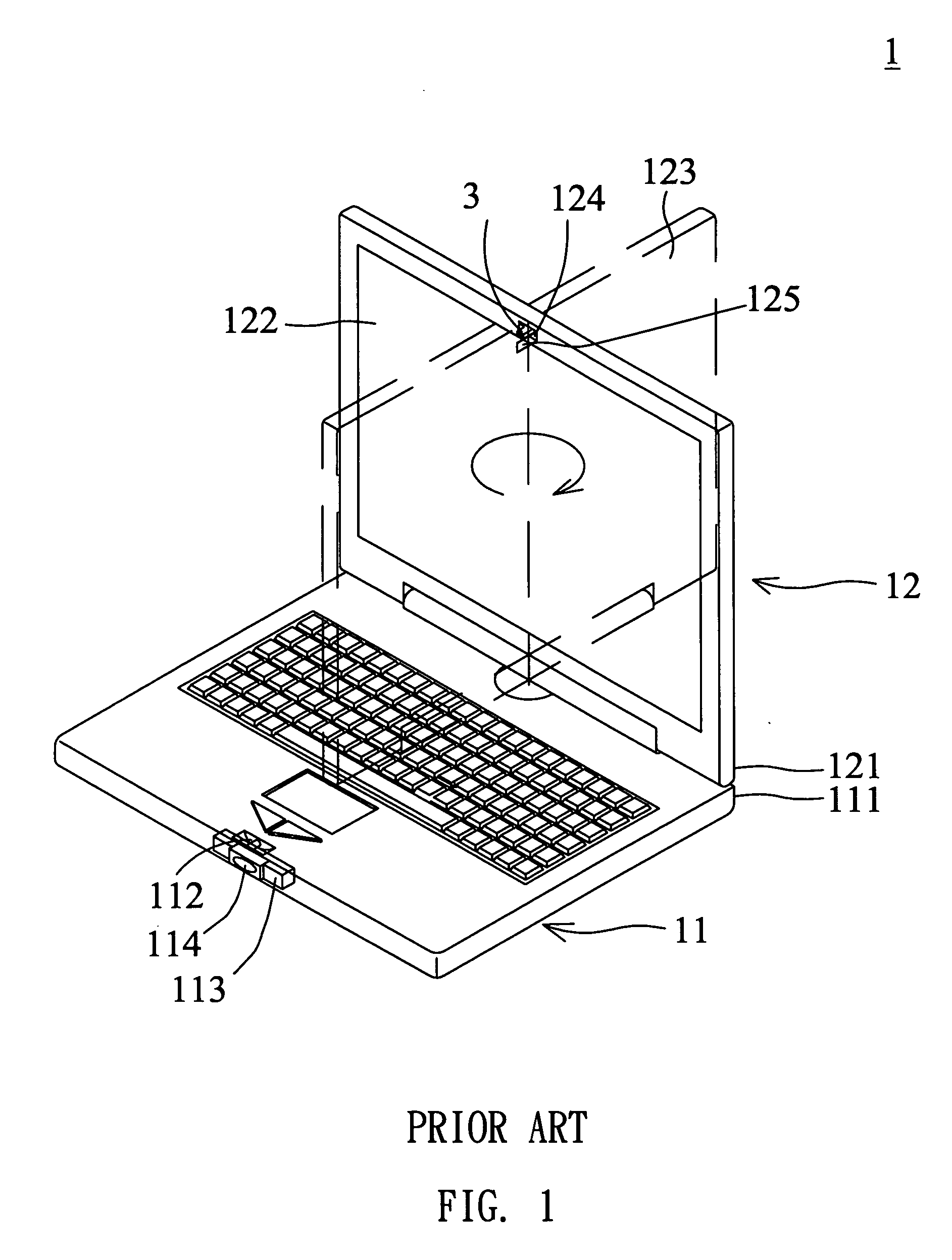
[0025] Hereinafter, a notebook is used as an example.

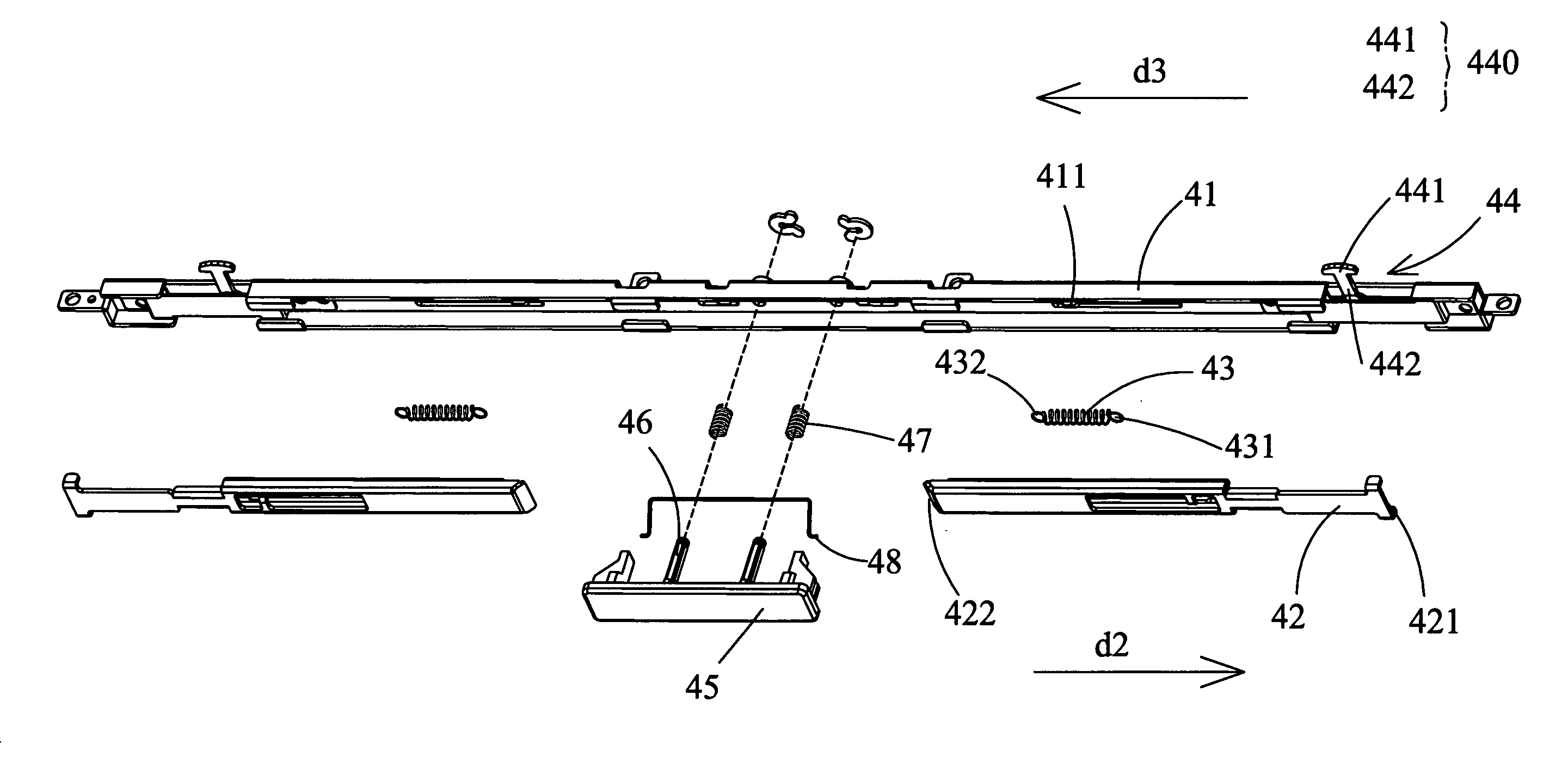
[0026] As shown in FIG. 5, the latch structure 4 according to an embodiment of the invention comprises a base 41, a connecting unit 42, a first elastomer 43, at least one hook unit 44 and a button 45. In this embodiment, the base 41 may be an iron plate, at least one part of a case or may comprise plastic material. The connecting unit 42 has a first side 421 and a second side 422, and the connecting unit 42 is disposed on the base 41.

[0027] The first elastomer 43 of the embodiment has a first end 431 and a second end 432. The first end 431 connects to the connecting unit 42 and the second end 432 connects to the base 41. The hook unit 44 is located at the first side 421 of the connecting unit 42, and the button 45 is located at ...


PUM


Abstract

A latch structure includes a base, a connecting unit, a first elastomer, at least one hook unit and a button. In this case, the connecting unit has a first side and a second side, and the connecting unit is disposed on the base. The first elastomer has a first end and a second end. The first end connects to the connecting unit and the second end connects to the base. At least one hook unit is located at the first side of the connecting unit. The hook unit has a moving member with a hook portion and a connecting portion, and the hook portion locates in a first site. The button is located at the second side of the connecting unit. When the hook portion does not locate in the first site, the button moves toward a first direction, the button pushes the connecting unit in a second direction, and the connecting unit touches the connecting portion. Accordingly, the hook portion turns to the first site.

Description

BACKGROUND OF THE INVENTION [0001] 1. Field of Invention [0002] The invention relates to a latch structure and, in particular, to a latch structure that has a hidden latch. [0003] 2. Related Art [0004] As the electronic age coming, the demand and the dependence of the electronic products increase. In this consumer-oriented time, not only a competed price of a good product, but also the character and convenience of the product are the key reasons for consumers to purchase or not. Therefore, manufacturers seriously investigate the products according to the demand of consumers. [0005] Hereinafter, a notebook is used as an example. Please refer to FIG. 1, the conventional notebook 1 includes a main body 11 and a cover 12, and the cover 12 is a display. A rear portion 121 of the cover 12 is connected to a rear portion 111 of the main body 11. The cover 12 has a display portion 122 and a back 123 of the cover 12. The cover 12 can be rotated and closed on the main body 11 with either the d...

Claims


Application Information

Patent Timeline
IPC IPC(8): E05C9/04E05C9/18G06F1/16H04M1/00H04M3/00H04M9/00
CPCE05C9/04G06F1/1679G06F1/162E05C9/1875Y10S292/37Y10T292/0849Y10T292/0854Y10T292/086Y10T292/0911Y10T292/0926Y10T292/0934Y10T292/0947Y10T292/1077
Inventor CHIANG, LING -YU
Owner ASUSTEK COMPUTER INC
Why Eureka
Try Eureka