

Organic material layer fabrication method
- Summary
- Abstract
- Description
- Claims
- Application Information
AI Technical Summary
Benefits of technology
Problems solved by technology
Method used
Image

Examples
first embodiment
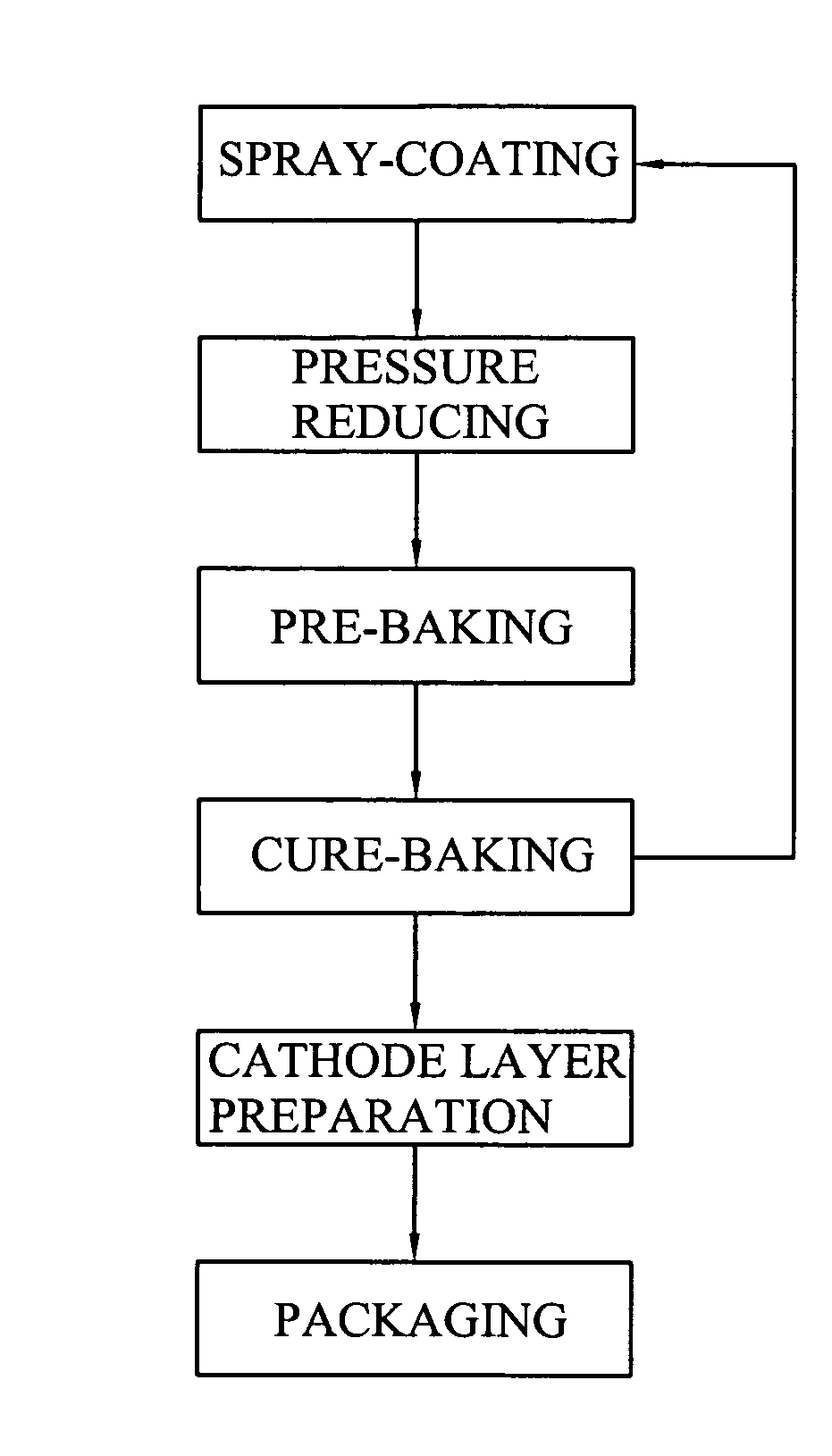
[0016]Referring to FIG. 1, an organic material layer fabrication method in accordance with the present invention is employed for the fabrication of an OLED (Organic Light Emitting Diode). The organic material layer fabrication method includes the follow steps:
[0017]Step I: Coating. At first, a well-cleaned ITO (Indium-Tin-Oxide) substrate is put in an enclosed chamber, and then an organic material layer is formed on the surface of the ITO substrate (or on the surface of another organic material layer already formed on the ITO substrate) by employing a spray coating technique to coat the surface of the ITO substrate with a layer of an organic material. The organic material layer can be an EML (Emitting Material Layer), EIL (Electronic Inject Layer), ETL (Electron Transport Layer), HTL (Hole Transport Layer), or HIL (Hole Inject Layer). The ITO substrate can be used as an anode layer for the OLED.
[0018]Step II: Pressure reducing. Lower the pressure in the enclosed chamber. When the pr...
second embodiment
[0023]Referring to FIG. 2, an organic material layer fabrication method in accordance with the present invention is for fabricating a batch of OLEDs. The organic material layer fabrication method includes the steps of:
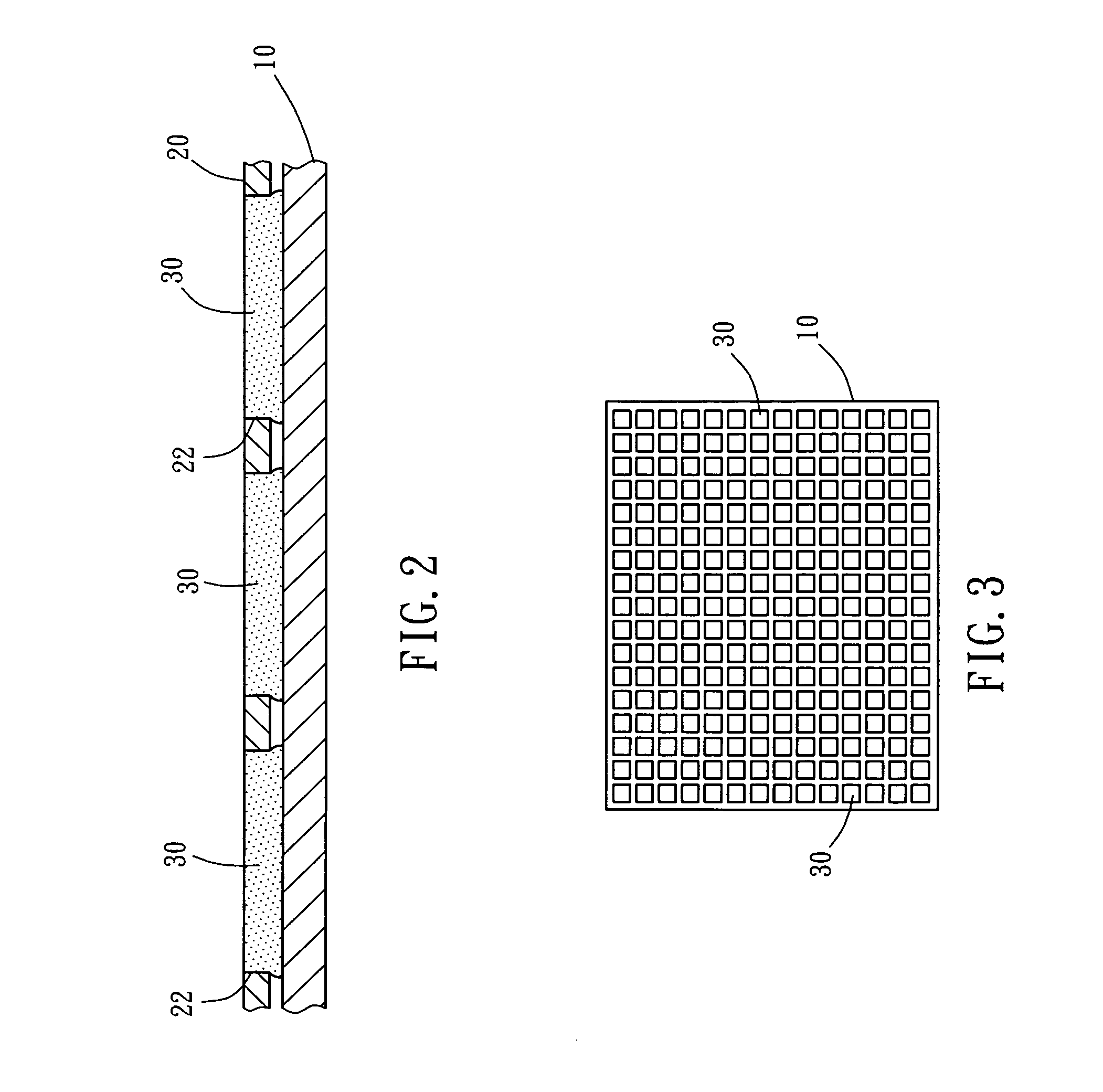
[0024]Step I: Put a well-cleaned ITO substrate 10 in an enclosed chamber, and then, as shown in FIG. 2, put a mask 20 having predetermined openings 22 on the surface of the substrate 10.
[0025]Step II: Spray-coat an organic material on the mask 20 to fill up the openings 22, thereby forming multiple organic material units 30 on the surface of the substrate 10.
[0026]Step III: Lower the pressure in the enclosed chamber. When the pressure in the enclosed chamber is lowered, the vaporization speed of the solvent contained in the surface of the organic material units 30 is accelerated, and therefore the solvent content is rapidly reduced. According to this embodiment, when the pressure in the enclosed chamber is lowered to the level below 0.5 atmosphere, the solvent content ...
PUM
 Abstract
Description
Claims
Application Information