[0032]In a general aspect, at least one embodiment in accordance with the present invention relates to a wafer transport system and a method for operating the same. More particularly, at least one embodiment relates to a wafer transport system with a low-capacity carrier and a method for operating the same. The embodiments and drawings provided here show different aspects of the present invention. However, the present invention is neither limited to any embodiment nor drawing thereof.
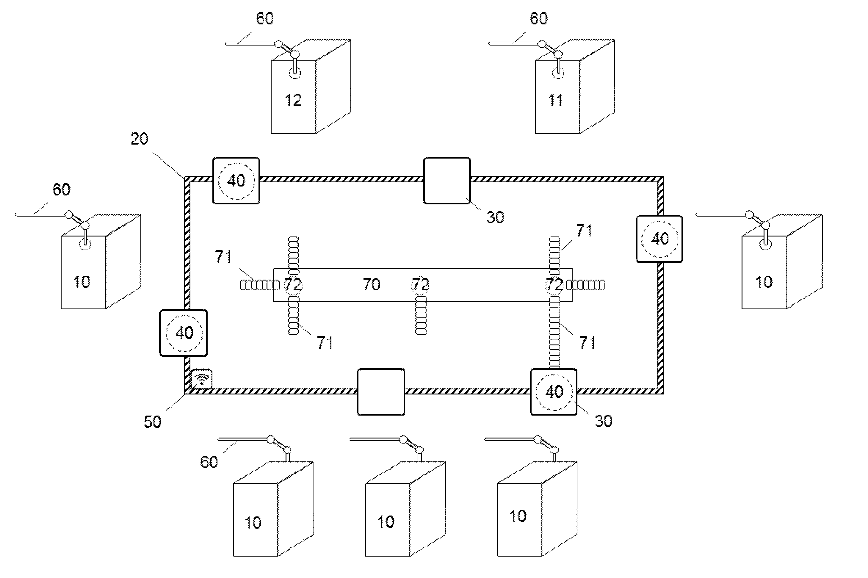
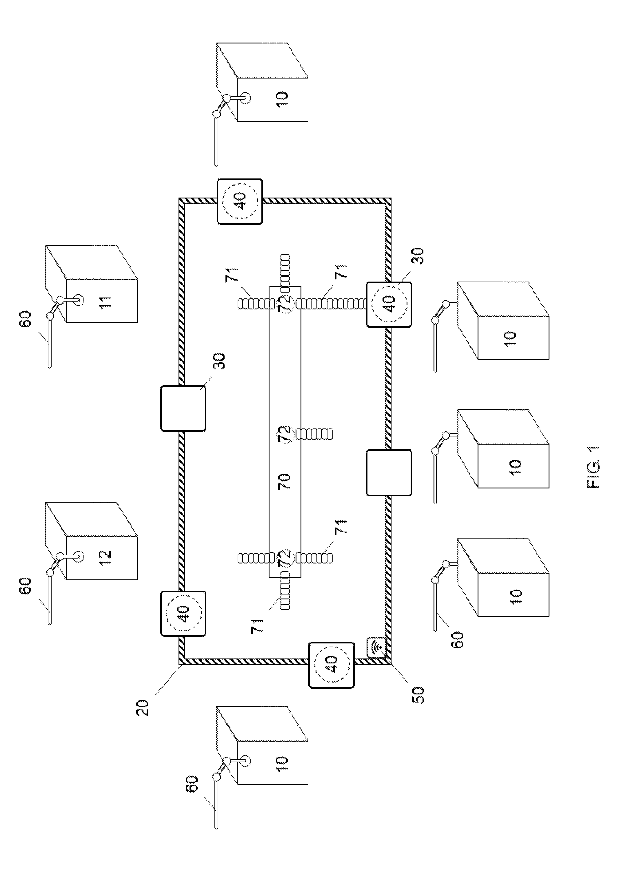
[0033]FIG. 1 is a schematic diagram illustrating an exemplary wafer transport system in accordance with at least one embodiment of the present invention. In FIG. 1, a wafer transport system may comprise at least one semiconductor apparatus 10, an entry port 11, an exit port 12, a track 20, a carrier 30, at least one positioning device 50, at least three transfer devices 60, and a cleaning device 70. The track 20 is located along the at least one semiconductor apparatus 10, the entry port 11, and the exit port 12. The carrier 30 is riding on the track 20 and is for housing and transporting the wafer 40 along the track 20. The positioning device 50 is connected to the track 20 for identifying and controlling the position of the carrier 30 on the track 20. The at least three transfer devices 60 are located between the at least one semiconductor apparatus 10 and the track 20, the entry port 11 and the track 20, and the exit port 12 and the track 20, respectively. The at least three transfer devices 60 are configured for transferring the wafer 40 between the at least one semiconductor apparatus 10, the entry port 11, and the exit port 12. The cleaning device 70 may comprise a pipe 71 and a pump 72. The pipe 71 connects the pump 72 to a first air valve 31 of the carrier 20 to clean the internal environment of the carrier 30.
[0034]FIGS. 2A-2B are the top perspective view and the bottom perspective view of a carrier 30 in accordance with at least one embodiment of the present invention. In some aspects of the aforementioned embodiments, the capacity of the carrier 30 is less than ten wafers. In some other aspects, the carrier 30 carries only one wafer 40 at a time. The internal environment of the carrier 30 may be a vacuum or be filled with clean gas.
[0035]The carrier 30 may comprise a first air valve 31, a carrier connector 33, a carrier door 34, and a carrier sensor 37. The first air valve 31 is configured to connect with a pipe 71 of a cleaning device 40 for cleaning the internal environment of the carrier 30. The carrier connector 33 is configured for mounting the carrier 30 to the track 20. Moreover, the carrier connector 33 may be deposited on different sides of the carrier 30 in accordance with the type of track 20 used in the wafer transport system. For example, the carrier connector 33 may be an overhead hoist and is deposited on the top surface of the carrier 30. The carrier door 34 is configured for the wafer 40 to enter or exit the carrier 30. The carrier sensor 37 may be a wafer sensor for detecting the amount of wafers 40 inside the carrier 30, or a RFID sensor capable of cooperating with a positioning device 50 in the wafer transport system. In some embodiments of FIGS. 2A-2B, the carrier 30 further comprises a second air valve 32 configured for expelling the excessive gas.
[0036]FIGS. 3A-3C are schematic diagrams of the exemplary carriers in accordance with some embodiments of the present invention. FIG. 3A illustrates a side-opening carrier which is similar to a conventional FOUP defined in SEMI E47.1 but further characterized by a first air valve 31, a smaller volume, and a reduced capacity. FIG. 3B illustrates a hinged carrier which may comprise a carrier cover 35, a carrier base 36, and a first air valve 31. The carrier cover 35 is attached to the carrier base 36 at one side to form a movable joint which provides the hinged carrier the ability to be opened and closed in a way similar to a book. In some embodiments of FIG. 3B, the hinged carrier further comprises an actuator for driving the hinged carrier to open or close. FIG. 3C illustrates a two-piece carrier which may comprise a carrier cover 35, a carrier base 36, a carrier connector 33, and a first air valve 31. The carrier cover 35 and the carrier base 36 are separated components and each connects to another indirectly. In some embodiments of FIG. 3C, the two-piece carrier is placed onto a track 20 in a wafer transport system. In the aforementioned embodiments, the wafer transport system transports the two-piece carrier by moving the track and opens the two-piece carrier by lifting the carrier cover 35 through the carrier connector 33.
[0037]FIG. 4 is a schematic diagram illustrating an exemplary transfer device in accordance with at least one embodiment of the present invention. The transfer device 60 in FIG. 4 may be a robot arm and is configured between a track 20 and a semiconductor apparatus 10. In some aspects, the wafer 40 may be temporarily exposed to the environmental contaminants and atmospheric gases when moving between the carrier and the semiconductor apparatus. Accordingly, a nozzle 61 may be configured onto the transfer device 60 for purging the wafer 40 with clean gas which forms a protective layer on the wafer 40 to protect the wafer 40 from the environmental contaminants.
[0038]FIG. 5 is a schematic diagram illustrating an exemplary cleaning device in accordance with at least one embodiment of the present invention. FIG. 5 shows a cleaning device 70 comprising a pipe 71 and a pump 72 for cleaning the internal environment of carrier 30. The pipe 71 connects the pump 72 to a first air valve 31 of a carrier 30. In some embodiments of FIG. 5, the pipe 71 is fixedly connected to the first air valve 31 and moves with the carrier 30 in a wafer transport system. In the aforementioned embodiments, the pump 72 is activated to clean the internal environment of the carrier 30 based on the requests for cleaning, and is inactivated when the cleaning process is completed. In some other embodiments of FIG. 5, the pipe 71 is fixedly connected to the first air valve 31 and moves with the carrier 30 in a wafer transport system. In the aforementioned embodiments, the pump 72 cleans the internal environment of the carrier 30 continuously during the movement of the carrier 30. In yet some other embodiments of FIG. 5, the pipe 71 is removably connected to the first air valve 31 of the carrier 70. In the aforementioned embodiments, the pipe 71 temporarily connects to the first air valve 31 when the cleaning device 70 is activated to clean the internal environment of the carrier 30, and disconnects from the first air valve 71 when the cleaning process is completed.
[0039]In an alternate embodiment of FIG. 5, a wafer transport system comprises a track 20, a carrier 30, an entry port 11, a first semiconductor apparatus, a second semiconductor apparatus, an exit port 12, and a cleaning device 70. The cleaning device 70 further comprises a first pipe, a second pipe, a third pipe, and a fourth pipe. The first pipe extends to the entry port 11; the second pipe extends to the first semiconductor apparatus; the third pipe extends to the second semiconductor apparatus; and the fourth pipe extends to the exit port 12. In this embodiment, a wafer 40 may be fed to the wafer transport system via the entry port 11. The wafer 40 is then transferred from the entry port 11 to the carrier 30 riding on the track 20, and the first pipe simultaneously connects to a first valve 31 of the carrier 30 to clean the internal environment of the carrier 30. In the next stage, the wafer 40 is transferred from the first semiconductor apparatus back to the carrier 30 once the first process is completed, and the second pipe simultaneously connects to the first valve 31 to clean the internal environment of the carrier 30. In the third stage, the wafer 40 is transferred from the second semiconductor apparatus back to the carrier 30 once the second process is completed, and the third pipe simultaneously connects to the first valve 31 to clean the internal environment of the carrier 30. In the final stage, the wafer 40 exits the wafer transport system via the exit port 12, and the fourth pipe connects to the first valve 31 to clean the internal environment of the carrier 30.
[0040]A risk arouse that the carrier 30 opened for receiving the wafer 40 from the semiconductor apparatus 10 may temporarily be exposed to the environmental contaminants. In some embodiments of FIG. 5, the cleaning device 70 cleans the internal environment of a carrier 30 by vacuuming the contaminated air inside the carrier 30. In some other embodiments of FIG. 5, the cleaning device 70 cleans the internal environment of a carrier 30 by filling the carrier 30 with clean gas and simultaneously expelling the contaminated air from the carrier 30 through a second air valve 32 of the carrier 30.
[0041]FIG. 6 is a schematic diagram illustrating an exemplary positioning device in accordance with at least one embodiment of the present invention. The positioning device 50 may be a sensor positioning controller, and multiple sensor positioning controllers may coexist in a wafer transport system to form a sensor array to increase the identification accuracy. In some embodiments of FIG. 6, the sensor positioning controller is an optical sensor connected with a track 20 for identifying the location of a carrier 30 on the track 20. The optical sensor may temporarily stop the movement of the track 20 based on an event that the carrier 30 is identified at a first location by the optical sensor. In some other embodiments of FIG. 6, the sensor positioning controller is a RFID sensor connected with a track 20 for identifying the location of a carrier. In the aforementioned embodiments, the carrier 30 may further comprise a RFID chip for assisting the identification processes of the sensor positioning controller.
[0042]FIG. 7 is a schematic diagram illustrating an exemplary positioning device in accordance with at least one embodiment of the present invention. The positioning device 50 may be a mechanical positioning controller, and multiple mechanical positioning controllers may coexist in a wafer transport system to increase the flexibility. In some embodiments of FIG. 7, the mechanical positioning controller is a retractable barrier configured on a track 20 for stopping the movement of a carrier 30 at a first location. To control the position of the carrier 30, the retractable barrier is activated and temperately extends across the moving path of the carrier 30 to stop the carrier 30 from moving. In some other embodiments of FIG. 7, the mechanical positioning controller is a movable recess on a track 20 for stopping the movement of a carrier 30 at the first location. As part of the track 20, the movable recess is activated to control the position of the carrier 30 by forming a recess on the track 20 which stops the carrier 30 from moving with the track 20, and is inactivated to release the carrier 30 by removing the recess.
[0043]FIG. 8 is a flow diagram illustrating a method for operating a wafer transport system in accordance with at least one embodiment of the present invention. In the wafer transport system, a wafer 40 may be transported along a track 20 via a carrier 30. While the carrier 30 moves, a positioning device 50 identifies the position of the carrier 30 and controls the carrier 30 to stop at a first location. The first location may be near to the opening of a semiconductor apparatus 10. Once the movement of the carrier 30 has been stopped, a transfer device 60 may be activated to transfer the wafer 40 from the carrier 30 to the semiconductor apparatus 10. After the wafer 40 is processed, the transfer device 60 is activated to transfer the wafer 40 from the semiconductor apparatus 10 back to the carrier 30. To clean the carrier 30 which has once been opened, a pipe 71 of a cleaning device 70 may subsequently connect to a first air valve 31 of the carrier 30 for cleaning the internal environment of the carrier 30. Finally, the pipe 71 disconnects from the first air valve 31 once the cleaning process is completed; and, the carrier 30 further transports the wafer 40 along the track 20 to a second location.
[0044]In some embodiments of FIG. 8, a nozzle 61 may be configured on the transfer device 60 for purging the wafer 40 with clean gas to protect the wafer 40 from the contaminants. In some embodiments of FIG. 8, there is a risk that the carrier 30 opened for receiving the wafer 40 from the semiconductor apparatus 10 may be temporarily exposed to the environmental contaminants. Therefore, the cleaning device 70 may clean the internal environment of a carrier 30 by vacuuming the contaminated air inside the carrier 30, or by filling the carrier 30 with clean gas and simultaneously expelling the contaminated air from the carrier 30 through the second air valve 32 of the carrier 30. In some other embodiments of FIG. 8, the positioning device 50 may be a sensor positioning controller or a mechanical positioning controller. The sensor positioning controller stops the movement of the track 20 based on that the carrier 30 is identified at the first location. The mechanical positioning controller is located at the first position on the moving path of the carrier 30 and blocks the movement of the carrier 30 at the first location when the mechanical positioning controller is activated.
[0045]In an alternate embodiment of FIG. 8, the wafer transport system comprises several carriers 30 and the method for operating is therefore modified. In the wafer transport system, a wafer 40 may be transported along a track 20 via a first carrier. While the first carrier is moving, a positioning device 50 identifies the position of the first carrier and controls the first carrier to stop at a first location. The first location may be near to the opening of a semiconductor apparatus 10. Once the movement of the first carrier has been stopped, a transfer device 60 may be activated to transfer the wafer 40 from the first carrier to the semiconductor apparatus 10. After the wafer 40 is processed, the transfer device 60 is activated to transfer the wafer 40 from the semiconductor apparatus 10 to a second carrier. A pipe 71 of a cleaning device 70 may connect to a first air valve 31 of the second carrier and a pump 72 of the cleaning device 70 is activated to clean the internal environment of the second carrier which has once been opened. Finally, the pipe 71 disconnects from the first air valve 31 when the cleaning process is completed and the second carrier further transports the wafer 40 to a second location.
[0046]FIG. 9 is a schematic diagram illustrating a method for operating a transfer device in accordance with at least one embodiment of the present invention. A positioning device 50 controls a carrier 30 to stop when the positioning device 50 identifies that the carrier 30 is located at a first location and aligned with the opening of the semiconductor apparatus 10. At the same time, a transfer device 60 may be activated to transfer a wafer 40 from the carrier 30 to a semiconductor apparatus 10 to process the wafer 40. Then, the transfer device 60 is activated again to transfer the wafer 40 from the semiconductor apparatus 10 to carrier 30 once the process is completed. In some embodiments, the transfer device 60 moves horizontally. Therefore, the transfer device may simply transfer the wafer without unnecessary movements such as lifting and rotation. The reduction of unnecessary movements may shorten the production cycle of a wafer and prevent the wafer from possible collisions.
[0047]FIG. 10 is a schematic diagram illustrating a method for operating a cleaning device in accordance with at least one embodiment of the present invention. A pipe 71 of a cleaning device 70 may extend and connect to a first air valve 31 of a carrier 30 when the transfer device 60 transferred a wafer 40 from a semiconductor apparatus 10 to the carrier 30. Subsequently, a pump 72 of the cleaning device 70 is activated to clean the internal environment of the carrier 30. Once the cleaning process is completed, the pipe 71 disconnects from the first air valve 31 and the carrier 30 then transports the wafer 40 away to a second location along the track 20
[0048]The figures and descriptions supra set forth only illustrated the preferred embodiments of the instant disclosure; however, the characteristics of the instant disclosure are by no means restricted thereto. All changes, alternations, combinations or modifications easily considered by the people skilled in the art are deemed to be encompassed within the scope of the instant disclosure delineated by the following claims.