Spiral balance device

Active Publication Date: 2019-01-31
NAKANISHI IND CO LTD
View PDF0 Cites 1 Cited by
  • Summary
  • Abstract
  • Description
  • Claims
  • Application Information

AI Technical Summary

Benefits of technology

[0016]As described above, the balance manufacturer preliminarily winds the torsion spring a predetermined number of rotations to apply pre-tension and lets it to stand for a predetermined period of time to relieve the change due to spring-back, and then provides the window manufacturer with the product. As mentioned above, si

Problems solved by technology

A sash window requires considerable effort in an opening and closing operation due to the weight of window and may sometimes move down from the state at rest by its own weight.
In this operation, since the pipe is fixed to the window frame and the operation site is narrow, a special tool is necessarily used, and it is difficult to securely grip the lower end of the spiral rod and appropriately rotate it.
Further, since the restoring force of the wound torsion spring always functions to rotate the spiral rod in a reverse direction, it is not easy to further rotate the spiral rod against the restoring force.
In addition, when the spring is wound, the spring tension varies by the function of spring-back and is therefore unstable immediately after winding the spring.
If the spring is set in the window under such condition that the spring tension is not yet stabilized, the ex

Method used


Image

  • Spiral balance device
  • Spiral balance device
  • Spiral balance device

Examples


Example

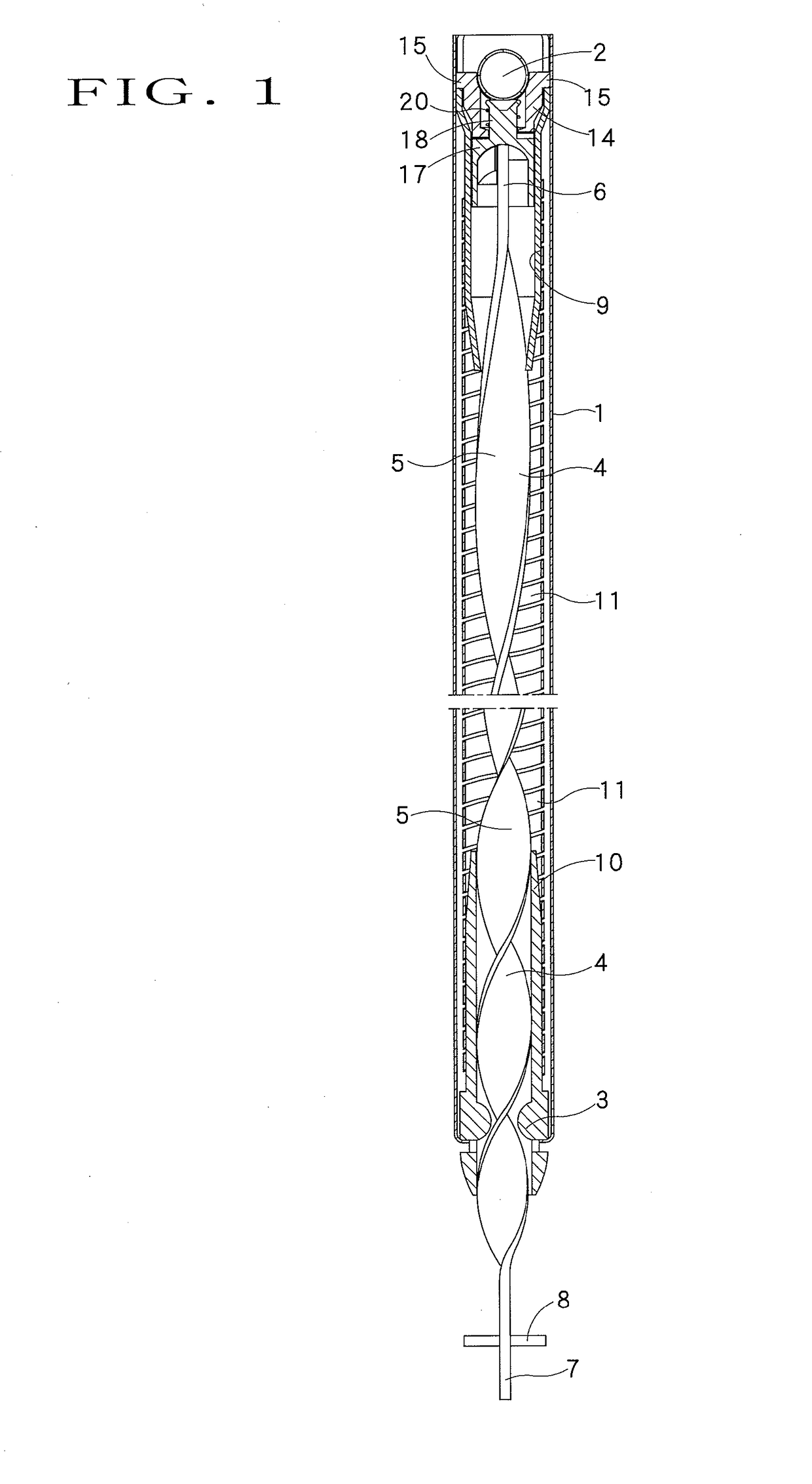
[0024]FIG. 1 shows an example of a spiral balance device according to one embodiment of the present invention to be applied to a sash window (not shown). As conventionally known, a pipe 1 configured to be housed in a window frame (not shown) of a sash window opens at its upper end and lower end and is fixed to the window frame by inserting a mounting screw (not shown) into a mounting hole 2 disposed near the upper end. At the lower end portion of the pipe 1, a coupling 3 is rotatably installed. Within the pipe 1, a spiral rod 5 having a screw section 4 formed in an axial direction is housed, and the spiral rod 5 extends in an axial direction through a slot at the central portion of the coupling 3. A first terminal or end portion 6 of the spiral rod 5 extends to near the upper end of the pipe 1, and a second terminal or end portion 7 of the spiral rod projects downwardly from the lower end of the pipe 1 and has a pin 8 attached thereto for connection with a window (not shown).

[0025]A...


PUM


Abstract

A spiral balance device for sash windows has a pipe inside of which extends a spiral rod having a screw section. A lower end of the spiral rod extends through a slot in a coupling rotatably disposed inside the lower end of the pipe and projects from the lower end of the pipe. A torsion spring has an upper end fixed near the upper end of the pipe and a lower end fixed to the coupling. A fixing member is fixed within the upper end of the pipe, and an adjustment member rotatably disposed below the fixing member engages with the upper end of the spiral rod. A ratchet mechanism disposed between the fixing member and adjustment member allows rotation of the adjustment member in a direction of winding the torsion spring and prevents rotation of the adjustment member in a direction of unwinding the torsion spring.

Description

FIELD OF THE INVENTION[0001]The present invention relates to a spiral balance device by which opening and closing of a sash window can be done easily and the window can be stopped at any desired position.BACKGROUND OF THE INVENTION[0002]A sash window requires considerable effort in an opening and closing operation due to the weight of window and may sometimes move down from the state at rest by its own weight. To prevent such situation, for example, U.S. Pat. No. 2,477,069 describes a spiral balance device in which a balanced load is generated corresponding to the weight of the window when the window is opened and closed to maintain balance with the weight of the window. This spiral balance device has a spiral rod and a torsion spring within a pipe. When the window is moved downwardly, the spiral rod moves downwardly within the pipe together with the window and winds a torsion spring, and the restoring force of the wound torsion spring functions to pull up the spiral rod and maintai...

Claims


Application Information

Patent Timeline
IPC IPC(8): E05D13/00
CPCE05D13/1253E05Y2900/148E05Y2201/492E05Y2201/638E05Y2600/14E05Y2600/324E05Y2600/33E05Y2800/26
Inventor NAKANISHI, YOSHIKAZU
Owner NAKANISHI IND CO LTD
Why Eureka
Try Eureka