Self-piercing nut

Inactive Publication Date: 2005-08-18
YUGENKAISHA SHINJO SEISAKUSHO
View PDF8 Cites 14 Cited by
  • Summary
  • Abstract
  • Description
  • Claims
  • Application Information

AI Technical Summary

Benefits of technology

[0009] Owing to the pilot portion end face whose outer diameter is larger than that of the lower end portion of the nut's main cylinder, the projected rim of a caulking die is capable of being aligned with the annular pressing face of a cylindrical striking punch. By virtue of this feature, the projected rim will ensure a strong and reliable caulking effect. As usual in operation of the conventional self-piercing nuts, the circular edge of a hole punched through a metal panel will forcibly be pressed and caulked into the annular groove. However, inherent in the pres

Problems solved by technology

An annular pressing face of this punch 34 is however not in axial alignment with the caulking rim 33, thus br

Method used


Image

  • Self-piercing nut
  • Self-piercing nut
  • Self-piercing nut

Examples


Embodiment Construction

[0021] Now some embodiments of the present invention will be described referring to the accompanying drawings.

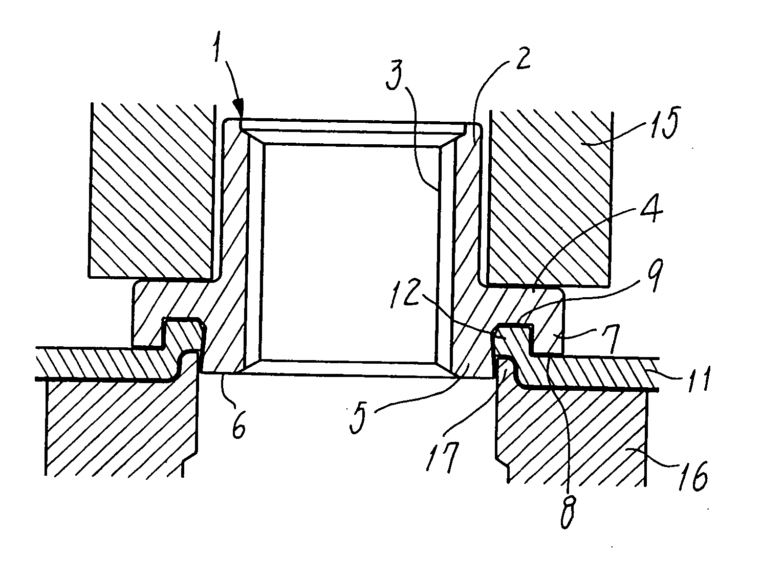
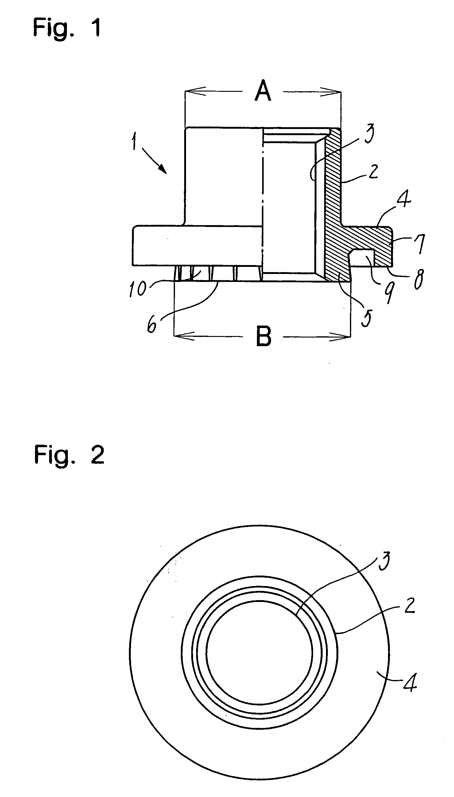
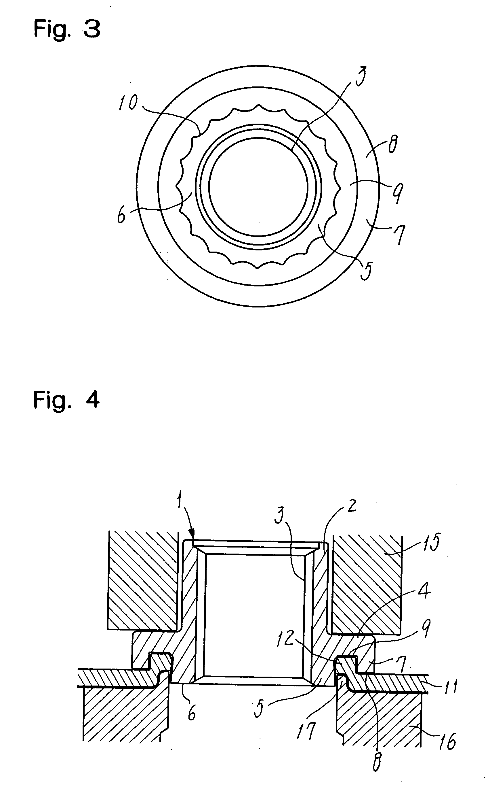
[0022] FIGS. 1 to 3 show a self-piercing nut 1 provided in an embodiment of the present invention. This nut 1 comprises a main threaded cylinder 2 having a threaded bore 3 and continuing to an expanded flange 4 that is formed integral with a lower end portion of this cylinder 2. A cylindrical pilot portion 5 integrally protrudes from a central region of the flange 4 so as to be coaxial with the main threaded cylinder 2 to surround the threaded bore. The pilot portion 5 has an end face for piercing a hole in a metal panel 11 (see FIG. 4). A skirt 7 formed as an outer peripheral and pendent wall of the flange does depend from the outer periphery of the flange 4. Thus, a seat portion is provided as a bottom face 8 of such a skirt 7, and an annular groove 9 is defined between the pilot portion 5 and the skirt. The pilot portion 5 has an end face 6 projected downwards a distance...


PUM


Abstract

A self-piercing nut has a main threaded cylinder (2) and a pilot (5) surrounding a threaded bore (3). The main cylinder has a lower end continuing to a flange (4), with the pilot (5) protruding from a central bottom of the flange so as to pierce a hole in a metal panel (11). A skirt (7) depends from the flange's periphery to serves as a seat (8) contacting the panel. An annular groove (9) is defined between the pilot (5) and skirt (7) such that the pilot is projected beyond the seat (8). The end face (6) of pilot has an outer diameter ‘B’ larger than that ‘A’ of the lower end of main cylinder (2). The outer periphery of pilot (5) is tapered to decrease its diameter inwards and to-wards the nut axis, and a corrugation (10) is formed in the outer periphery or in the inner periphery of skirt (7).

Description

FIELD OF THE INVENTION [0001] The present invention relates to a self-piercing nut comprising a nut body for piercing a hole in a metal panel such that a generally circular edge of the hole is caulked to bite and fix the nut in position, even if the panel is a relatively soft aluminum plate or the like. BACKGROUND OF THE INVENTION [0002] In these years, larger seat areas have been wanted from a viewpoint of mechanical strength for the seat portions of self-piercing nuts designed for attachment to the body panels of automobile cars. This requirement is important in a case wherein soft metal plates such as aluminum plates prone to undergo deformation are used to make the cars lighter in weight. [0003] The Japanese Patent Laying-Open Gazette No. 2001-304226 shows an example of the self-piercing nut whose seat portion is of an increased area to meet the requirement mentioned above. [0004] As shown in FIGS. 9 and 10, the prior art self-piercing nut 21 comprises a central threaded bore 23...

Claims


Application Information

Patent Timeline
IPC IPC(8): F16B37/04F16B37/06
CPCF16B37/068
Inventor SHINJO, TADASHI
Owner YUGENKAISHA SHINJO SEISAKUSHO
Why Eureka
Try Eureka