Contact tonometer using MEMS technology

a technology of contact tonometer and mems, which is applied in the field of microelectromechanical systems, can solve the problems of deteriorating into total blindness of patients, difficult to imagine how difficult and lonely it would be, and elevated eye pressure damage the optic nerv

Inactive Publication Date: 2005-08-18
REICHERT
View PDF25 Cites 12 Cited by
  • Summary
  • Abstract
  • Description
  • Claims
  • Application Information

AI Technical Summary

Problems solved by technology

It is hard to imagine how difficult and lonely it would be if you lost visual contact with the colorful world.
This elevated eye pressure damages the optic nerve and can deteriorate into total blindness for the patient.
It is obvious that this method cannot be used in routine eye examinations.
The disadvantages of the Schiotz tonometer were: patient apprehension, anesthesia required, good patient cooperation needed, corneal abrasions possible, required a physician (not staff members), and significant aqueous displacement.
If the flow of aqueous is impeded along its route, IOP will rise which can damage the optic nerve.
The cornea has limited rigidity rather than being perfectly elastic, the cornea is wet and the surface tension of the tear film tends to pull the applanating surface onto the cornea.
Goldmann and Schmidt noted that the measurements are only reliable in eyes with normal human corneas.
These equations are not valid in eyes of examined animals because the corneas of the animals' eyes are different from the human corneas.
MEMS devices have been contemplated for use in the past for placement within the eye or on a contact lens to sense IOP due to their small size; however, the unexpected advantages of the use of MEMS technology in both hand held and table mounted tonometers have not been recognized nor has there been any recognition of the manner in which MEMS technology can be used to improve tonometers.

Method used


Image

  • Contact tonometer using MEMS technology
  • Contact tonometer using MEMS technology
  • Contact tonometer using MEMS technology

Examples


Embodiment Construction

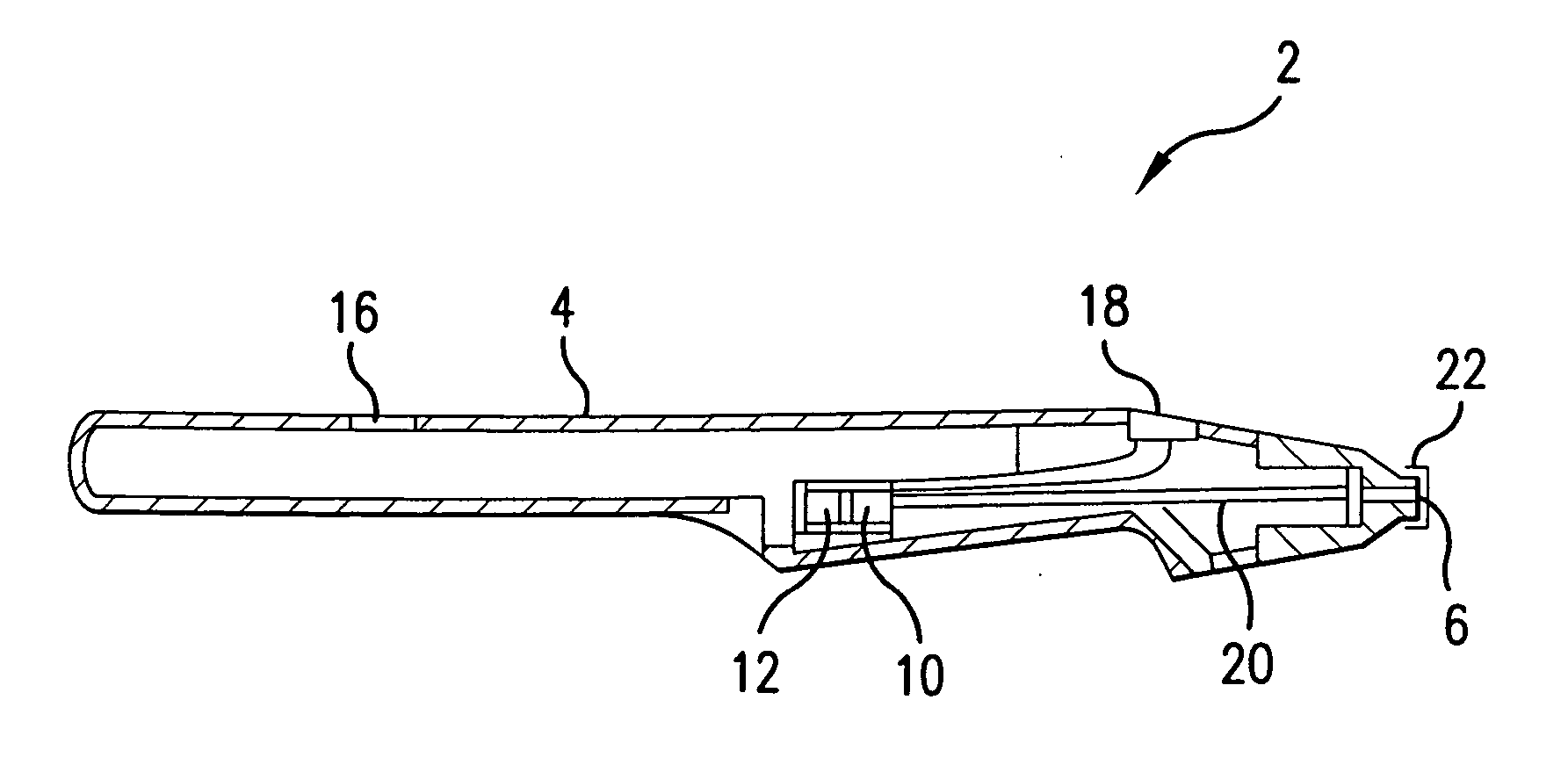
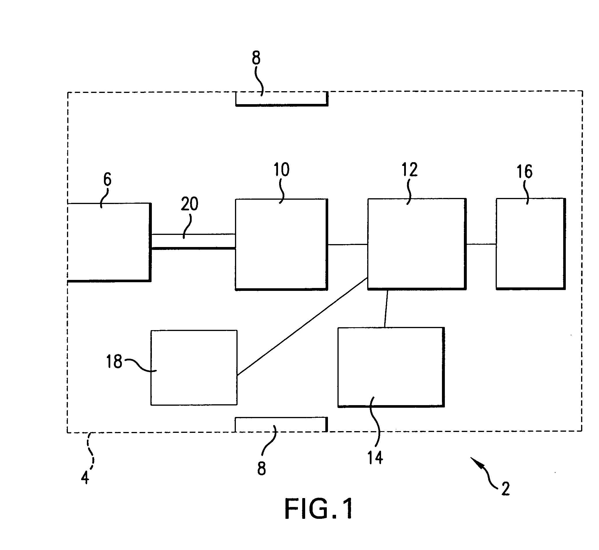
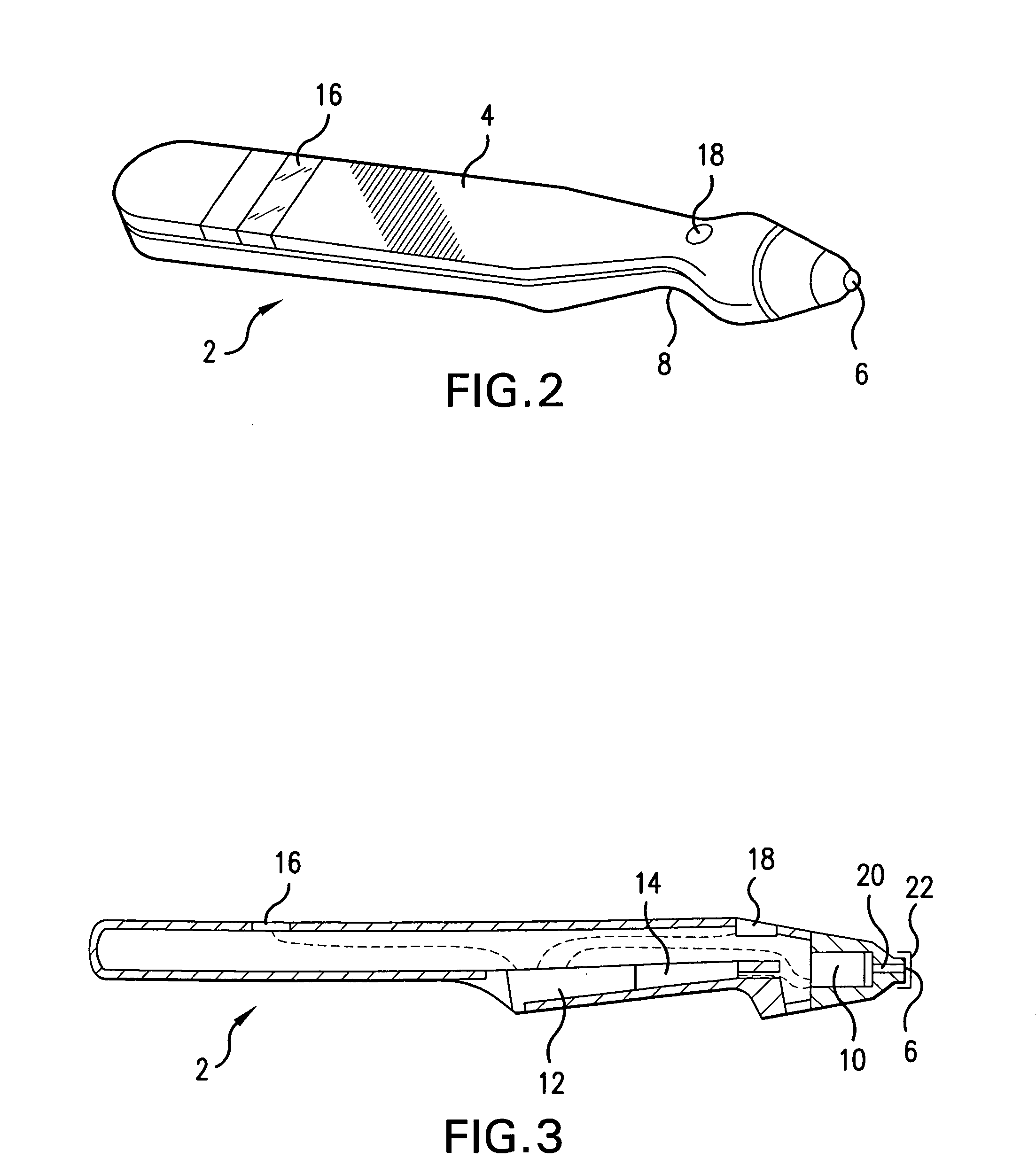
[0074] As shown schematically in FIG. 1, contact tonometer 2 according to the invention includes a housing 4 having a distal or contact end 6 and, in a preferred embodiment, a gripping portion 8 proximal to the contact end 6. The contact tonometer 2 includes a MEMS device 10 acting as a transducer to measure the force applied by the contact end 6 to the patient's cornea and to produce an electrical signal representative thereof. The contact tonometer 2 includes electronics and / or microprocessor (“electronics”) 12, a source of power 14 and a display 16. In the preferred embodiment, the electronics 12, source of power 14 and display 16 are integral parts of the housing 4. However, in another embodiment, they may be separate from housing 4.

[0075] Electronics 12 processes electrical signals from the MEMS device 10 and supplies a signal to display 16 causing display 16 to display information representative of the determined IOP. The source of power 14 is connected to the electronics 12 ...


PUM


Abstract

An contact tonometer for sensing intra-ocular pressure (IOP) including a micro-electro-mechanical system (MEMS) device forming a transducer / sensor at or in contact with a contact end of the tonometer where the cornea is contacted and electronics receiving an electrical signal from the transducer and processing the signal to produce a display indicative of intra-ocular pressure.

Description

BACKGROUND OF THE INVENTION [0001] 1. Field of the Invention [0002] The present invention relates to the use of micro-electro-mechanical systems (“MEMS”) technology in the fabrication of pressure or force sensing monitors for the human body in the medical field and, more particularly, for sensing intra-ocular pressure (IOP). [0003] 2. Brief Discussion of the Related Art [0004] The eye is one of the most important organs of the human body. It is hard to imagine how difficult and lonely it would be if you lost visual contact with the colorful world. Cataracts, glaucoma and age-related macular degeneration are the three major diseases of the eye that rob older people of vision. Among these three, glaucoma is the leading cause of blindness, accounting for 12 percent of new cases of blindness each year in the United States. Glaucoma is often called the “silent thief” because most people who develop glaucoma cannot feel it until it is too late to be mitigated by medical treatment. [0005] ...

Claims


Application Information

Patent Timeline
Patent Type & Authority Applications(United States)
IPC IPC(8): A61B3/16
CPCA61B2562/028A61B3/16
Inventor BRUCE, JOHN C.CROCETTA, MICHAEL J. JR.
Owner REICHERT
Why Eureka
Try Eureka