Delivery system for a medical device

a delivery system and medical device technology, applied in the field of delivery systems, can solve the problems of not allowing the user to adjust or tighten the components of the system, and the system described by wilson does not permit the re-adjustment of the different components of the mechanism

Active Publication Date: 2005-08-18
ABBOTT LAB INC
View PDF73 Cites 199 Cited by
  • Summary
  • Abstract
  • Description
  • Claims
  • Application Information

AI Technical Summary

Benefits of technology

[0015] In still further accordance with the invention, the sheath can include a first material at its proximal end and a second, different material at its distal end. The sheath can define a first diameter at its proximal end, and a second, different diameter at its distal end. The sheath can include an outer layer and an inner layer and a reinforcing layer disposed between the outer layer and the inner layer. In still further accordance with the invention, the tip can include a radiopaque portion.
[0016] In further accordance with the invention, the delivery system can further include an adjustment member configured to move the inner member with respect to the sheath. The adjustment member can include an adjustment lock. The adjustment lock preferably has a locked position to prevent the inner member from being displaced longitudinally with respect to the sheath and an unlocked position to allow the inner member to be displaced longitudinally with respect to the sheath. The adjustment member preferably includes an adjustment hypotube disposed about the proximal end of the inner member. Preferably, the adjustment hypotube is attached to the inner member. The adjustment member can further include a hub fixedly attached to the adjustment hypotube.

Problems solved by technology

For example, while delivery systems for delivering medical devices such as stents have existed for a long time, to date, no systems have been developed that allow the user to adjust or tighten the components of the system after shipment of the device to the physician.
As with other systems known in the art, the system described by Wilson does not permit re-adjustment of the different components of the mechanism after sterilization and shipment.

Method used


Image

  • Delivery system for a medical device
  • Delivery system for a medical device
  • Delivery system for a medical device

Examples


Embodiment Construction

[0049] Reference will now be made in detail to the present preferred embodiments of the invention, examples of which are illustrated in the accompanying drawings. The method and corresponding steps of the invention will be described in conjunction with the detailed description of the apparatus. The methods and apparatus presented herein are used for delivering a medical device, such as a stent, stent graft or filter, to a desired location in a patient. In accordance with the invention, it is possible and desired to provide a system for delivering such devices that is relatively inexpensive to manufacture and easy to use.

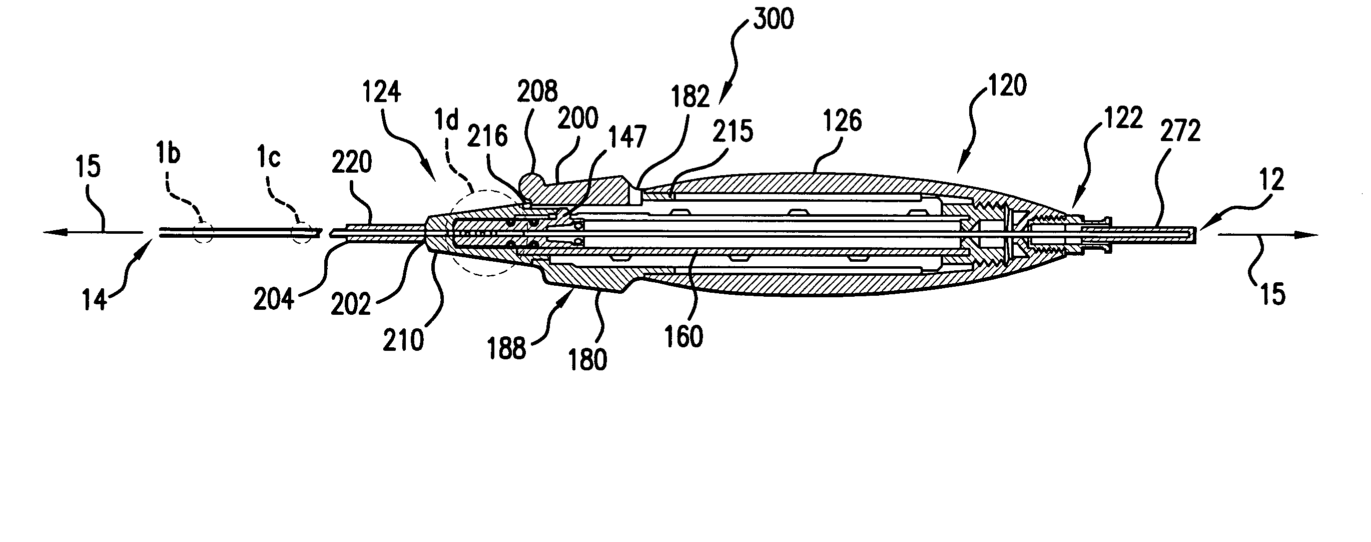
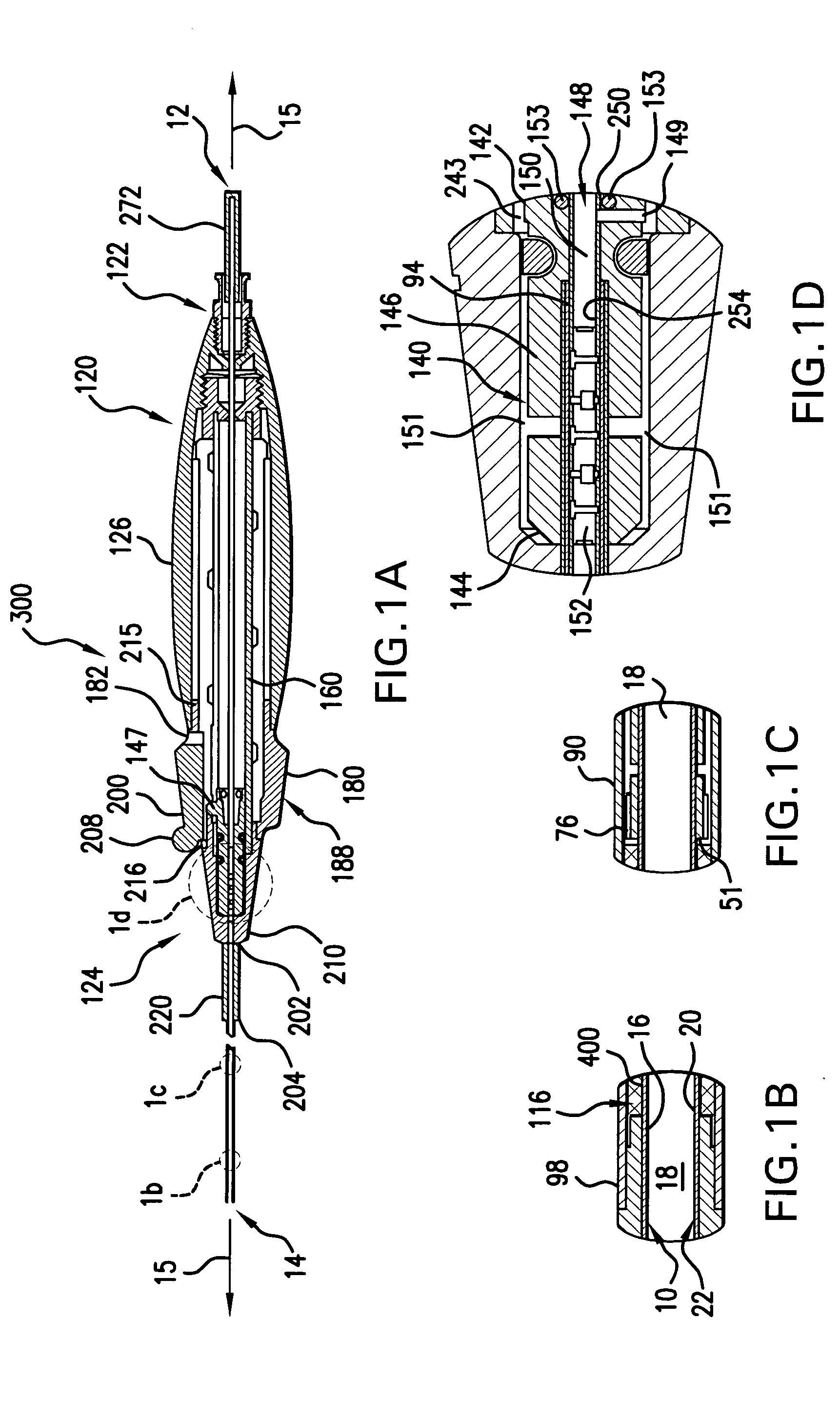
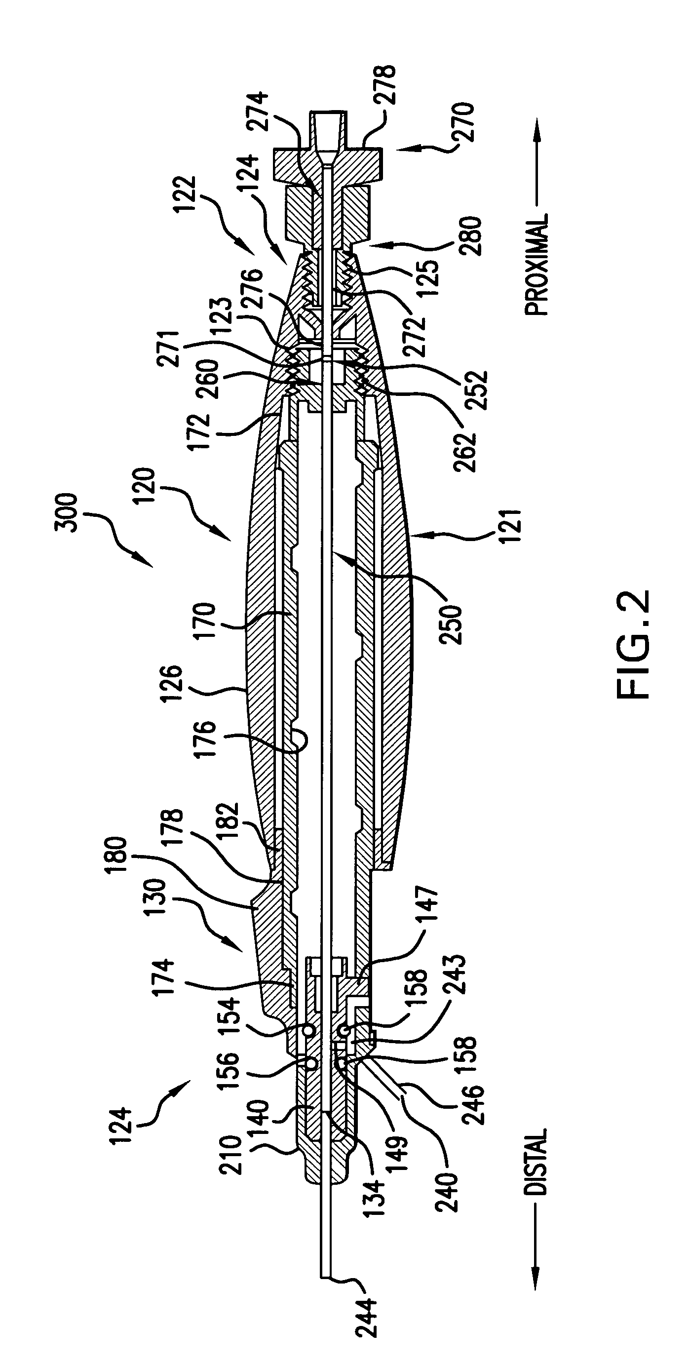
[0050] For purpose of explanation and illustration, and not limitation, an exemplary embodiment of the delivery system for a medical device in accordance with the invention is shown in FIGS. 1(a) - 1(d) and is designated generally by reference character 1. This exemplary embodiment or portions thereof is also depicted in FIGS. 2, 4-6(a), 7-9, and 13-14(a). Additiona...


PUM


Abstract

The invention is directed to a delivery system for delivering a medical device. The delivery system includes an inner member having a proximal end and a distal end. The inner member defines a longitudinal axis between the proximal end and the distal end. A tip is formed at the distal end of the inner member. A bumper is freely disposed on the inner member. The bumper has a proximal end and a distal end. A seat is defined between the tip and the distal end of the bumper. Additionally, a sheath is disposed about the inner member, the sheath having a proximal end and a distal end. The sheath is movable from a first sheath position substantially covering the seat, and a second sheath position axially offset to expose the seat. The invention also includes a handle in contact with the proximal end of the inner member.

Description

BACKGROUND OF THE INVENTION [0001] 1. Field of the Invention [0002] The present invention relates to a delivery system for delivery of one or more medical devices, such as a stent, stent-graft or filter. Particularly, the present invention is directed to a delivery system including an inner member having a tip, a bumper freely disposed on the inner member, a sheath disposed about the inner member, and a handle attached to the inner member. The invention also includes a related method for assembling a delivery system. [0003] 2. Description of Related Art [0004] A variety of systems are known for intraluminal delivery of a medical device within a patient. However, there remains a need for continued improvement of such known delivery systems. For example, while delivery systems for delivering medical devices such as stents have existed for a long time, to date, no systems have been developed that allow the user to adjust or tighten the components of the system after shipment of the dev...

Claims


Application Information

Patent Timeline
Patent Type & Authority Applications(United States)
IPC IPC(8): A61F2/06A61F2/84A61M29/00
CPCA61F2002/9517A61F2/95A61F2/9517
Inventor JEN, JIMMYLASSER, AMELIASHUMER, DANIEL H.HAHN, JUERGEN ANTONSCHNEIDER, RALPHGRATHWOHL, HARTMUT
Owner ABBOTT LAB INC
Why Eureka
Try Eureka