Aroma diffuser
a diffuser and diffuser technology, applied in air humidification systems, heating types, lighting and heating apparatuses, etc., can solve the problems of high risk of fire, long use time, and rise in the temperature of the outer shell of the main body
- Summary
- Abstract
- Description
- Claims
- Application Information
AI Technical Summary
Benefits of technology
Problems solved by technology
Method used
Image

Examples
embodiment 1
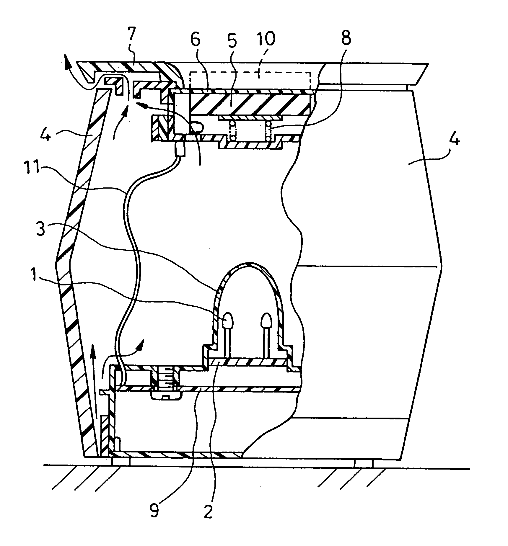
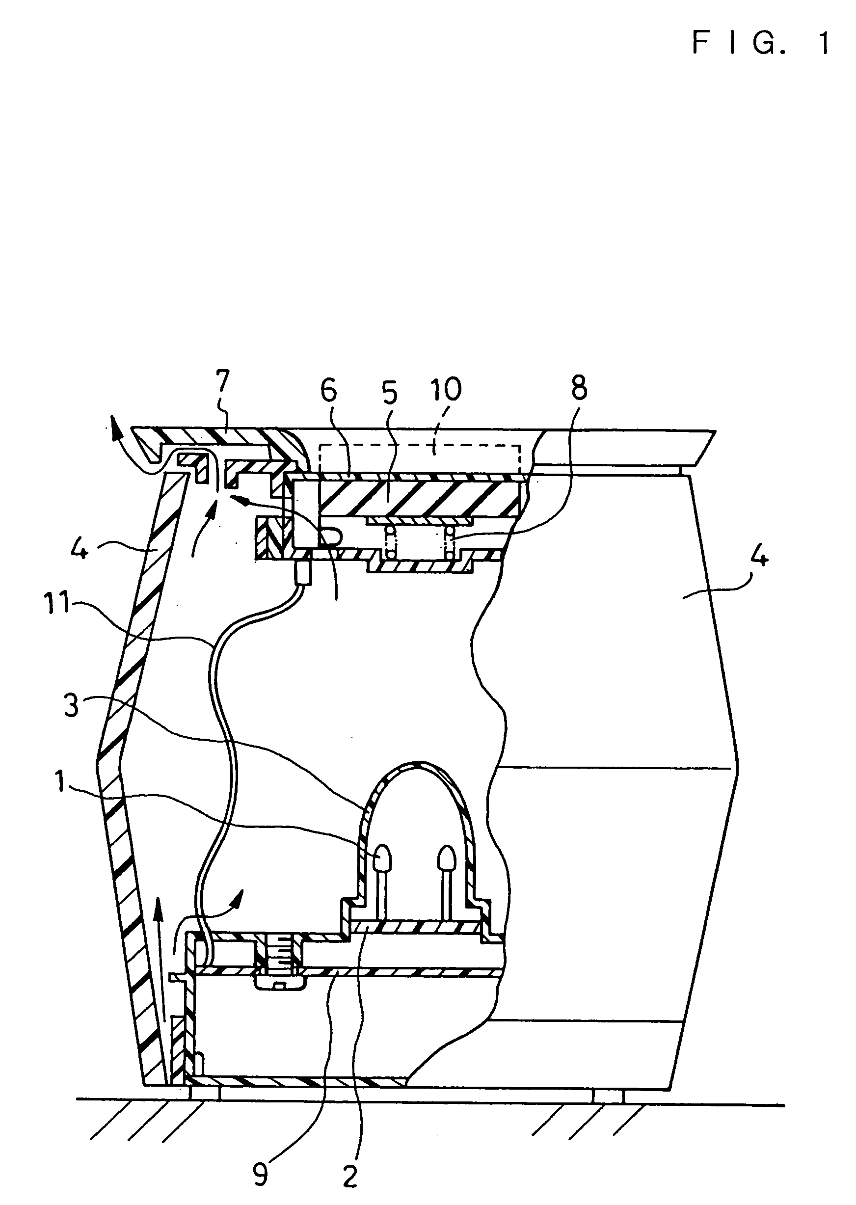
[0039]FIG. 1 is a vertical cross-sectional view showing the configuration of an aroma device in accordance with Embodiment 1.
[0040] In the figure, numeral 1 designates LEDs serving as a light source. Four LEDs are mounted on an LED circuit board 2 at intervals of 90 degrees (mutual angles in the case when a polar coordinate system wherein the center line (not shown) of the aroma device is used as an axis is imagined in FIG. 1 and when the intersection points (four points) between a plane perpendicular to the center line (to the face of the paper) and the LEDs 1 are represented by polar coordinates). Numeral 3 designates a first cover for covering the LEDs 1 and for allowing light to be diffused and transmitted therethrough. Numeral 4 designates a second cover, provided outside the first cover 3, for allowing light to be diffused and transmitted through at least part or the whole of the side face thereof, and the second cover has openings at both ends in the vertical direction. In F...
embodiment 2
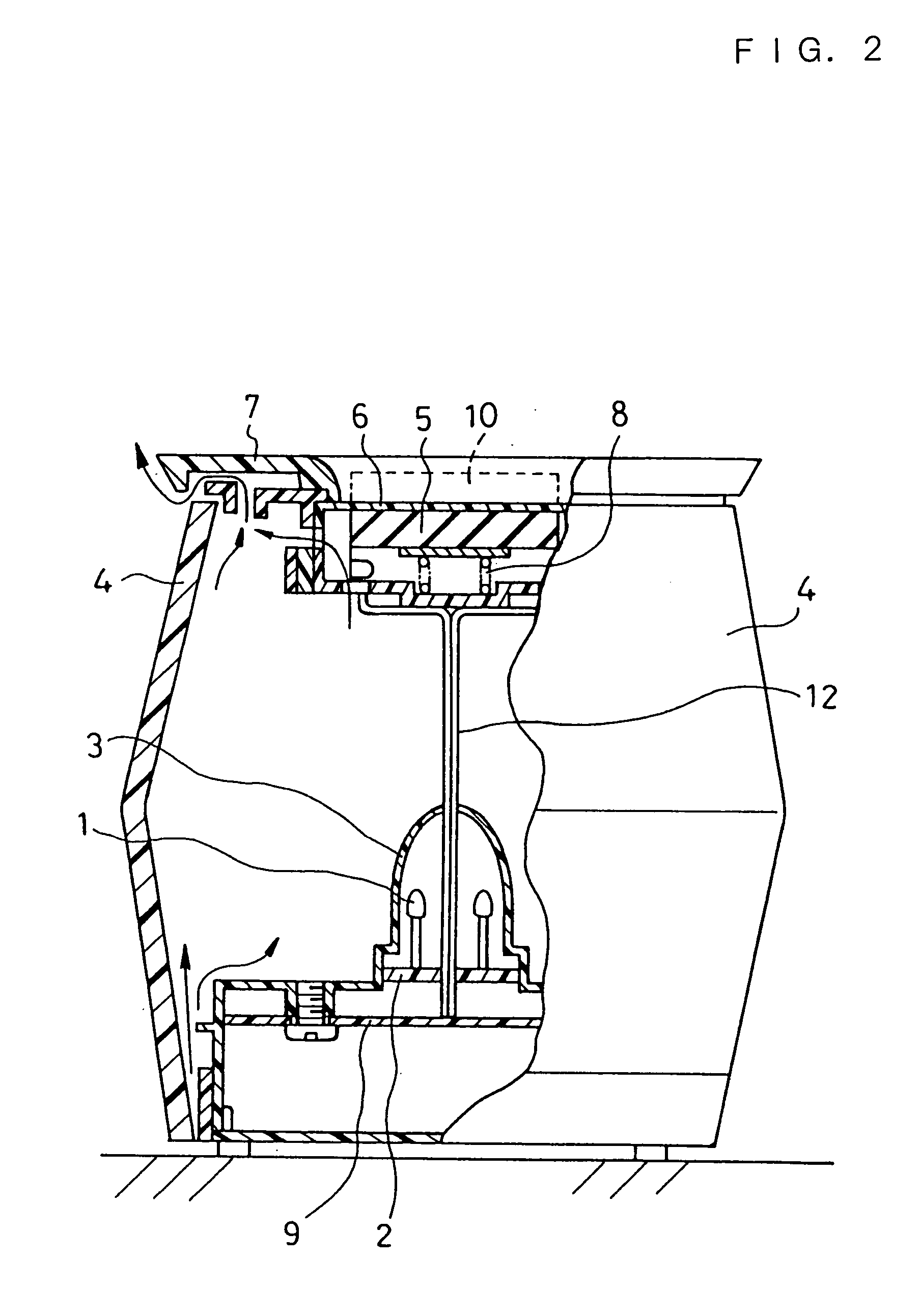
[0052]FIG. 2 shows an aroma device in accordance with Embodiment 2. Since the basic configuration thereof is the same as that of Embodiment 1, the same components are designated by the same numerals, their explanations are omitted, and the differences will be described mainly.
[0053] In this embodiment, LEDs 1, three in number, are mounted on an LED circuit board 2 at intervals of 120 degrees (mutual angles in the case when represented by a polar coordinate system similar to that of Embodiment 1). In addition, the upper portion of a first cover 3 through which the light of the LEDs 1 is diffused and transmitted and the LED circuit board 2 are each provided with a hole of 4 mm in diameter, and heater wires 12 pass therethrough. The heater wires 12 are raised from the center of each of the LEDs 1. A heater 5 is disposed above the LEDs 1 and connected to the heater wires 12.
[0054] The operation of the aroma device having the above-mentioned configuration is similar to that of Embodime...
embodiment 3
[0057]FIG. 3 shows an aroma device in accordance with Embodiment 3. The basic configuration thereof is the same as that of Embodiment 2. The same components are designated by the same numerals, their descriptions are omitted, and the differences will be described mainly.
[0058] Heater wires 12 raised from the center of each of LEDs 1 are bound by a holding pipe 13. In addition, a PTC heater is used as a heater 5.
[0059] In the aroma device having the above-mentioned configuration, the heater wires 12 are bundled by the holding pipe 13; hence, the heater wires 12 are formed into one and can be raised more perpendicularly, whereby the shadows due to the heater wires 12 can be made invisible.
[0060] Furthermore, by making the color of the holding pipe 13 similar to and paler than the light emission color of the LEDs 1, the shadows due to the heater wires 12 can be made further invisible.
[0061] Moreover, since a PTC heater is used as the heater 5, the temperature of the heater 5 can be...
PUM
 Abstract
Description
Claims
Application Information
 - R&D Engineer
- R&D Manager
- IP Professional
- Industry Leading Data Capabilities
- Powerful AI technology
- Patent DNA Extraction
Browse by: Latest US Patents, China's latest patents, Technical Efficacy Thesaurus, Application Domain, Technology Topic.
© 2024 PatSnap. All rights reserved.Legal|Privacy policy|Modern Slavery Act Transparency Statement|Sitemap