Electronic camera equipped with an automatic focusing function

a technology of automatic focusing and electronic cameras, applied in the field of automatic focusing methods and automatic focusing control functions, can solve the problems of inability to take images in a highly precise focus state, snapshots will be flawed, and the apparatus is practically in a focused state in an incredibly short tim

Active Publication Date: 2005-08-25
CASIO COMPUTER CO LTD
View PDF9 Cites 50 Cited by
  • Summary
  • Abstract
  • Description
  • Claims
  • Application Information

AI Technical Summary

Problems solved by technology

In particular, after performing focus lens drive based on a phase difference detection signal by a phase difference detection method and then performing a focus lens drive based on an AF rating value by a contrast detection method, the apparatus is practically in a focused state in an incredibly short time.
However, in a conventional digital camera, etc. using AF processing consistent with a hybrid method although a focus state can be rapidly realized and with high precision to shoot an object (take an image of a subject), when the AF sensor (ranging sensor) is obstructed (blocked from the field of view) there is a high probability that the snapshot will be flawed or the image could not be taken in a highly precise focus state.

Method used


Image

  • Electronic camera equipped with an automatic focusing function
  • Electronic camera equipped with an automatic focusing function
  • Electronic camera equipped with an automatic focusing function

Examples


first embodiment

[0032] A. Digital Camera Configuration

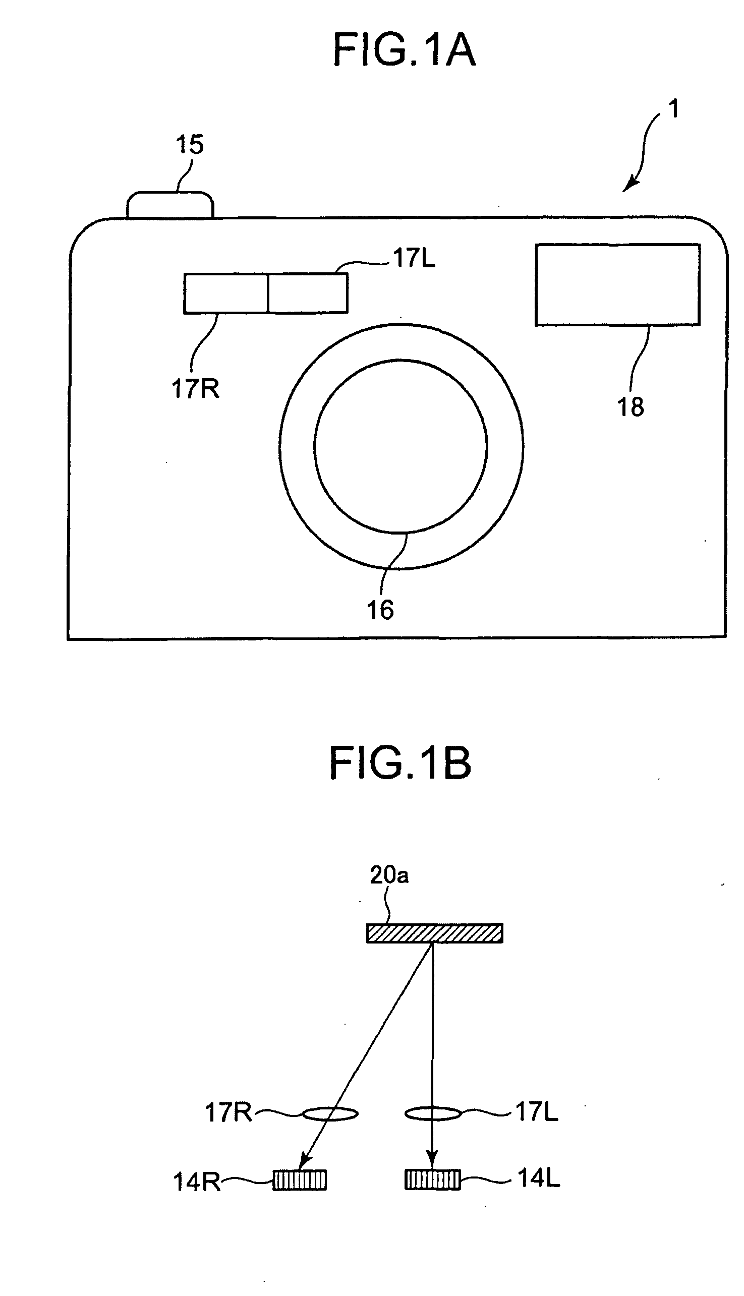
[0033]FIG. 1A shows the external outline appearance of a digital camera 1 which actualizes the automatic focusing method of the present invention. The front side of the digital camera 1 is configured with a shooting lens 16, a lens 17 (17R, 17L) for auto focus (AF) and a strobe light section 18. The top side of the digital camera 1 is equipped with a shutter button 15 which can be halfway depressed and fully depressed.

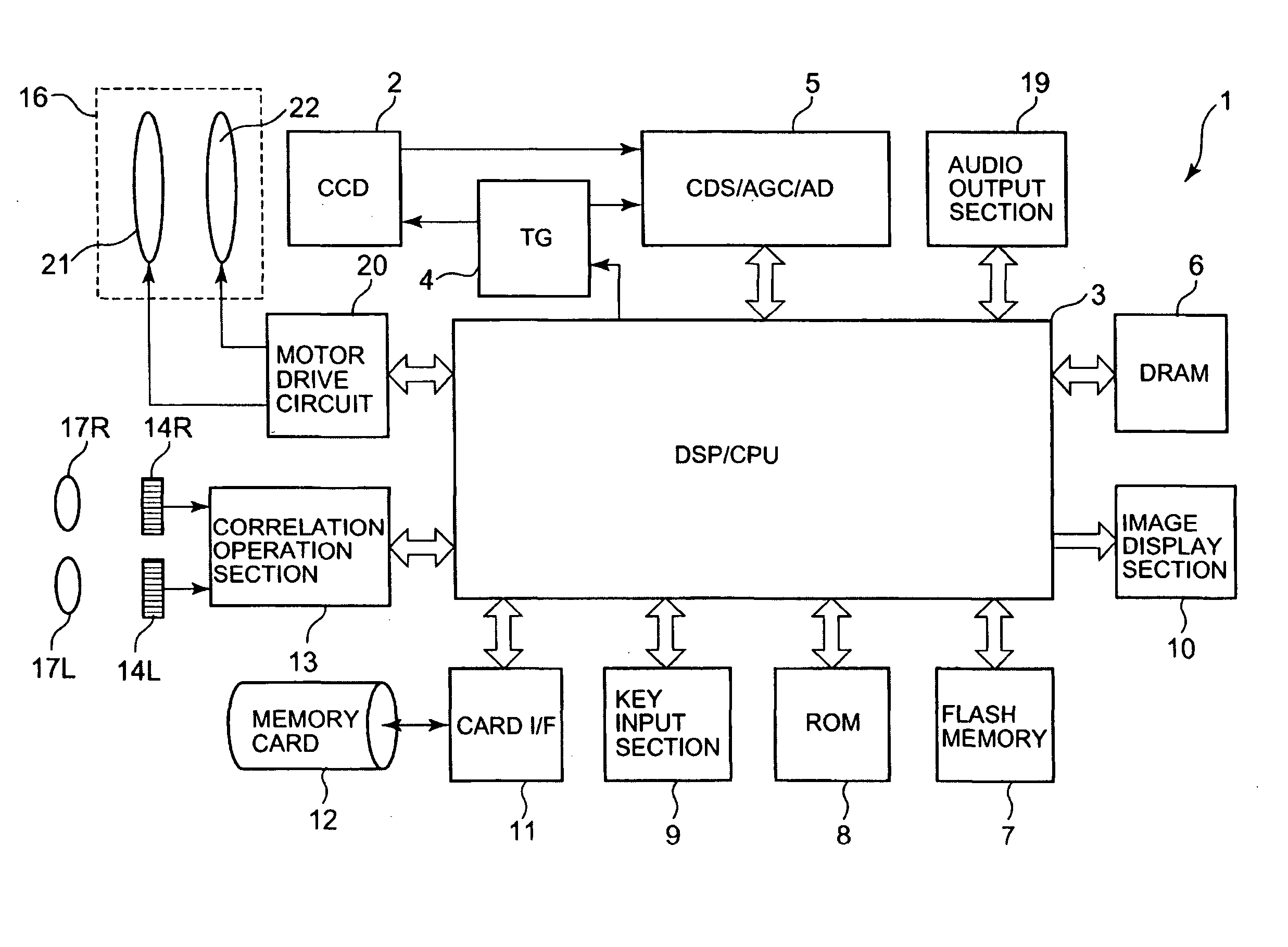
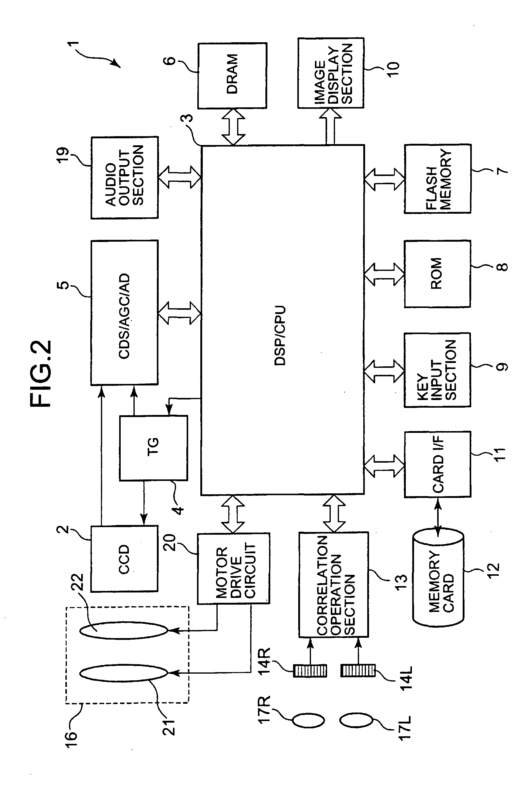
[0034]FIG. 2 is a block diagram showing the electrical outline configuration of the digital camera 1 which actualizes the automatic focusing method of the present invention.

[0035] The digital camera 1 comprises a CCD (Charge-Coupled Device) 2, a DSP / CPU (Digital Signal Processor / Central Processing Unit) 3, a TG (timing generator) 4, a unit circuit 5, a DRAM (Dynamic Random Access Memory) 6, a flash memory 7, a ROM (Read-Only Memory) 8, a key input section 9 (including the shutter button 15), an image display section 10, card I / F...

second embodiment

[0092] Next, the second embodiment will be explained.

[0093] The second embodiment is a digital camera which employs an AF processing function according to a hybrid method, wherein appropriate AF processing is performed by the operation judging whether or not the difference between the illuminance (light intensity) detected by the sensor array and the illuminance detected by the CCD 2 is greater than a constant threshold value.

[0094] D. Digital Camera 1 Configuration

[0095] The second embodiment also actualized the automatic focusing device of the present invention by using the digital camera 1 which has the same composition as the apparatus shown in FIG. 1.

[0096] The digital camera 1 in the second embodiment configuration features differ with the first embodiment in the following points.

[0097] When the DSP / CPU 3 judges that the shutter button 15 is halfway depressed, the illuminance detected by the sensor array 14 and the illuminance detected by the CCD 2 are stored in the DRAM ...


PUM


Abstract

A user by halfway depressing (S12) a shutter button acquires (S13, S14) the output OR and the output OL of a sensor array. Subsequently, an operation judges whether or not the absolute value of the difference between the output OR and the output OL is greater than a threshold value (S15). When judged greater than a threshold value, an operation initiates a warning notification to the user (S17, S18) and AF processing by a contrast detection method is performed. Meanwhile, when judged less than a threshold value, the focus lens is moved so focus can be performed toward the distance to an object with a phase difference detection method (S20). Then, the focus lens is moved from the existing focus lens position by a narrow range and the focus lens is moved to the lens position constituting the highest contrast value (S21).

Description

CROSS-REFERENCE TO RELATED APPLICATION [0001] This application is based upon and claims the benefit of priority from the prior Japanese Patent Application No. 2004-049431, filed Feb. 25, 2004, the entire contents of which is incorporated herein by reference. BACKGROUND OF THE INVENTION [0002] 1. Field of the Invention [0003] The present invention relates to an automatic focusing method and an automatic focusing control function, which for example is configurable for use in a digital camera equipped with an automatic focusing function (commonly abbreviated as “auto focus function” or “AF function”). [0004] 2. Description of the Related Art [0005] Recently, in step with the advances of digital camera technology, a digital camera with AF functions consistent with a hybrid method (also referred to as a “hybrid system”) which jointly utilizes a contrast AF function with a phase difference AF function has begun to appear in the electronic camera industry. Accordingly, AF processing can be...

Claims


Application Information

Patent Timeline
Patent Type & Authority Applications(United States)
IPC IPC(8): G02B7/28G03B13/36G02B7/30G02B7/36G03B13/32G03B17/18H04N5/225H04N5/232H04N101/00
CPCH04N5/23212H04N23/672H04N23/673H04N23/634
Inventor ONOZAWA, MASARU
Owner CASIO COMPUTER CO LTD
Why Eureka
Try Eureka