
Recording medium mounting apparatus

Inactive Publication Date: 2005-08-25
ALPS ALPINE CO LTD
View PDF3 Cites 9 Cited by
  • Summary
  • Abstract
  • Description
  • Claims
  • Application Information

AI Technical Summary

Benefits of technology

[0013] The present invention has been made to solve the above conventional problems. It is therefore an object of the present invention to provide a recording medium mounting apparatus comprising a loading mechanism which makes it possible to automatically carry a recording medium having a connector.
[0014] Further, it is another object of the present invention to provide a recording medium mounting apparatus which can prevent a recording medium from being carried into the inside of the apparatus, if the recording medium is loaded in an abnormal state.
[0015] Further, it is still another object of the present invention to provide a recording medium mounting apparatus which can reliably perform miniaturization and connection between connectors.

Problems solved by technology

However, the above-mentioned fixed hard disk drives cannot cope with a large increase in capacity that is being rapidly progressed.
However, according to the disclosure in Japanese Unexamined Patent Application Publication No. 4-47554, there is a problem in that a user is burdened with inconvenience in use that a user should manually mount a connector at a recording medium, such as a removable hard disk, on a connector at a recording medium mounting apparatus.
Further, since the entire recording medium cannot be accommodated into the apparatus due to the manual insertion, a part of the recording medium is apt to protrude to the outside of the apparatus.
For this reason, if an external force is applied to a part of the recording medium, there is a problem in that data errors or data destruction is caused.
Moreover, if a recording medium is loaded in an abnormal orientation, it is necessary to prevent the recording medium from being carried into the inside of the apparatus.

Method used


Image

  • Recording medium mounting apparatus
  • Recording medium mounting apparatus
  • Recording medium mounting apparatus

Examples


Embodiment Construction

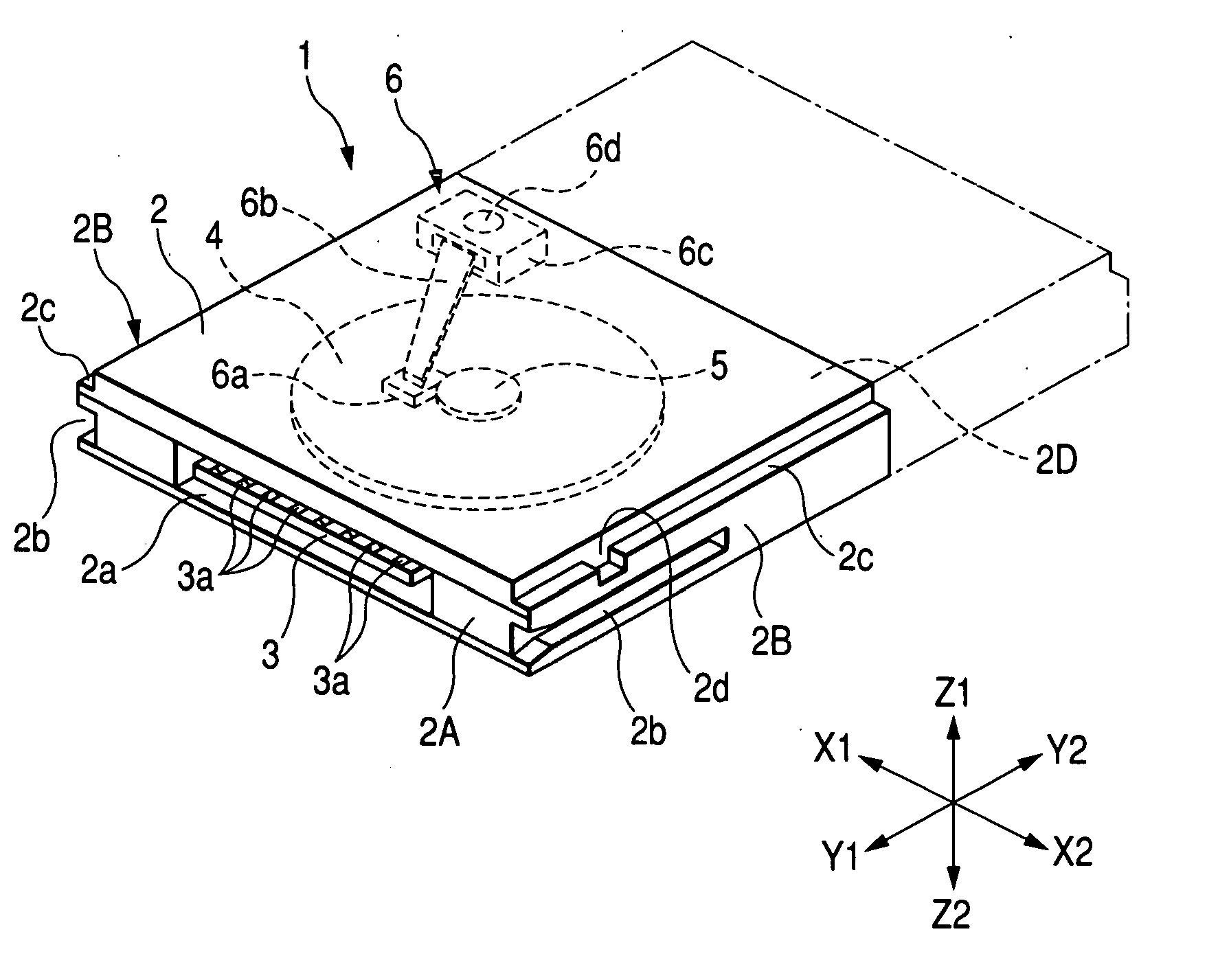
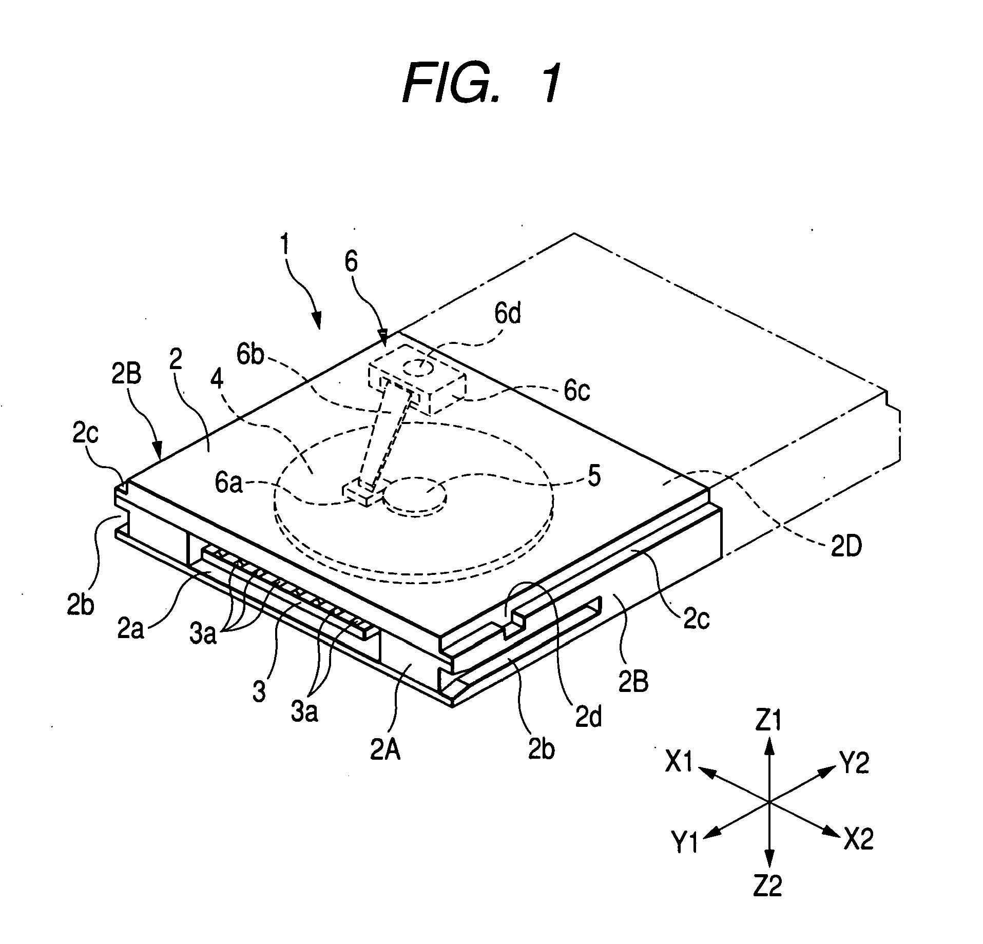
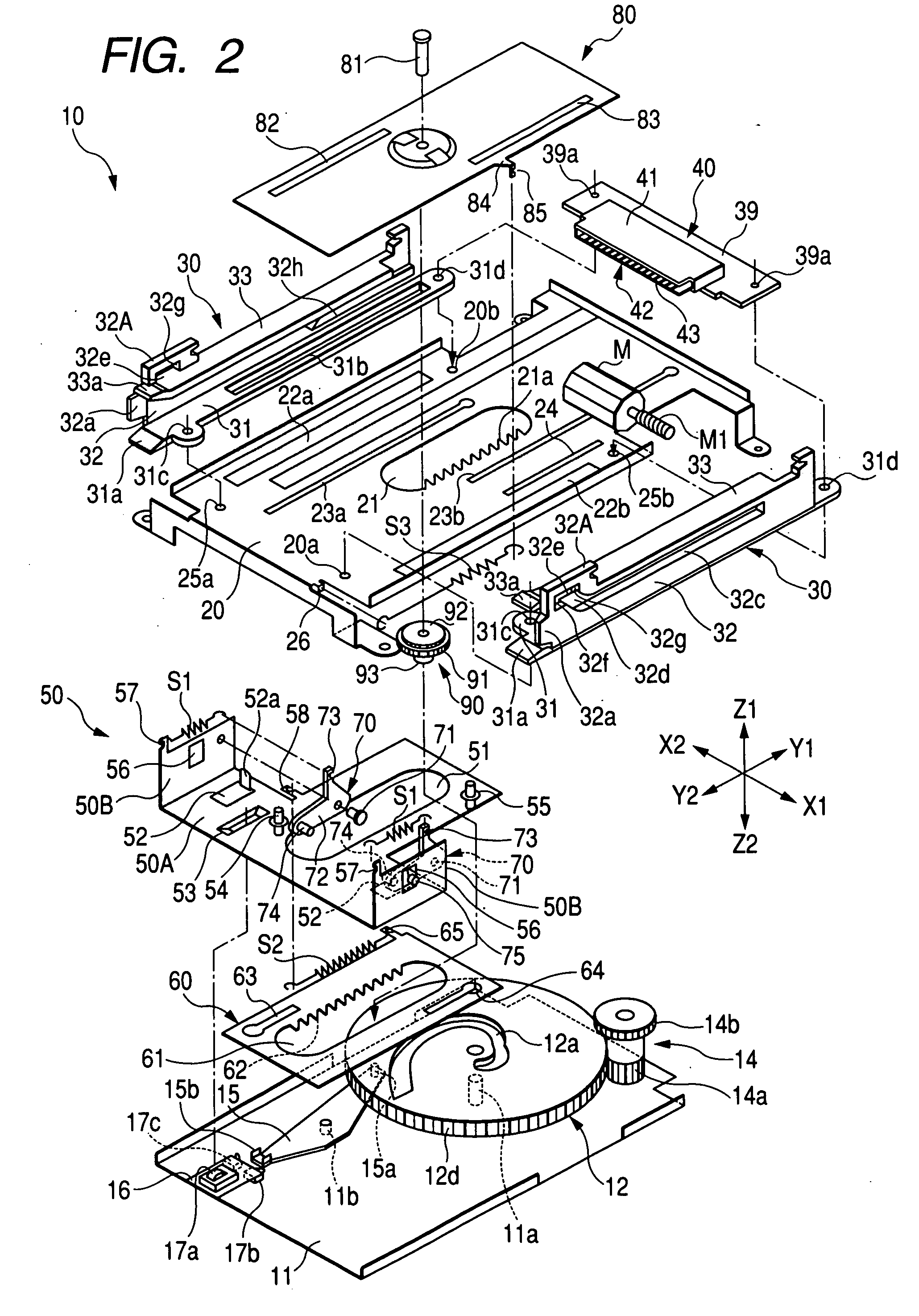
[0071]FIG. 1 is a perspective view showing the appearance of a recording medium to be mounted on a recording medium mounting apparatus, FIG. 2 is an exploded perspective view showing an internal structure of the recording medium mounting apparatus according to an embodiment of the present invention, FIG. 3 is a plan view showing a lower chassis and a cam member, and FIG. 4 is a cross-sectional view mainly taken along the line A1-A1 in FIG. 3.

[0072] First, a recording medium to be mounted on a recording medium mounting apparatus will be described.

[0073] What is to be mounted on the recording medium mounting apparatus shown after FIG. 2 is, for example, a removable recording medium 1 as shown in FIG. 1. The recording medium 1 has a thin cubic cartridge 2. The recording medium 1 includes, for example, a standardized removable hard disk, such as 1.8-inch-type (small-sized) hard disk which is indicated by solid lines in FIG. 1, a 2.5-inch-type (large-sized) hard disk which is longer th...


PUM


Abstract

When a recording medium is inserted into an insertion part, a locking part of a pull-in member locks a concave part of the recording medium because a pressed part is pressed to move a moving member. Simultaneously, a first switching member is switched, and a cam member rotates to move a power transmission means into the inside of an apparatus (Y1-direction). Thereby, since the moving member having the pull-in member mounted thereon also moves, the recording medium can be carried into the inside of the apparatus. If the recording medium is abnormally orientated, the locking part can lock the concave part. Therefore, the recording medium can be prevented from being carried into the inside of the apparatus.

Description

BACKGROUND OF THE INVENTION [0001] 1. Field of the Invention [0002] The present invention relates to a recording medium mounting apparatus into which a recording medium such as a removable hard disk is loaded, and more specifically, to a recording medium mounting apparatus comprising an auto-loading mechanism. [0003] 2. Description of the Related Art [0004] Recently, while networks which are rapidly spreading are made broadband, the cost of high-performance personal computers (PCs) is reduced, digital still cameras and digital video cameras are permeated into homes, and broadcasts are digitalized, information including videos, music, and pictures are being digitalized in our neighborhood. Further, information processing equipments, such as televisions and telephones, which can be connected to personal computers and Internets on television screens also have entered a new phase which goes beyond conventional categories. [0005] Up to now, 3.5-inch-type fixed hard disk drives are used a...

Claims


Application Information

Patent Timeline
IPC IPC(8): G06F1/16G06F1/18G11B17/04G11B25/04G11B33/12
CPCG06F1/184G06F1/187G11B33/121G11B25/043G11B17/051A61M3/0225A61M3/0241A61M3/0266A61M3/0279
Inventor ITO, KIYOYUKI
Owner ALPS ALPINE CO LTD
Learn More