Serial transmission system, its transmission-side circuit, and its reception-side circuit

a transmission system and transmission circuit technology, applied in the field of serial transmission systems, can solve the problems of inability to select the number of channels and the data rate optimum, and achieve the effect of reducing the number of channels and reducing the number of data rates

Active Publication Date: 2005-08-25
ASAHI KASEI ELECTRONICS CO LTD
View PDF1 Cites 6 Cited by
  • Summary
  • Abstract
  • Description
  • Claims
  • Application Information

AI Technical Summary

Benefits of technology

[0006] A serial transmission system of the present invention is an LVDS system for converting N (N is a natural number; the same is applied hereafter) types of parallel signals into serial signals and sending / receiving the converted serial signals between a driver and a receiver through M (M≦N; the same is applied hereafter) signal lines, includes transmission-side switching selection means for selecting a driver to be used in accordance with the number of signal lines M used for transmission / reception and reception-side switching selection means for selecting a receiver to be used in accordance with the number of signal lines M used for transmission / reception, and performs transmission / reception by using a driver and receiver selected by the transmission-side switching selection means and reception-side switching selection means. According to this configuration, it is possible to select the number of channels and a data rate optimum for the impedance of a signal line without fixing the number of signals used for transmission / reception. Moreover, it is possible to switch transmission speeds and the number of channels in accordance with the transmission speed of a signal line using a transmission system. Therefore, it is possible to use an optimum transmission speed without changing transmission-side devices and reception-side devices.

Problems solved by technology

This case has a disadvantage that it is impossible to select the number of channels and a data rate optimum for the impedance of a signal line used for transmission / reception.

Method used


Image

  • Serial transmission system, its transmission-side circuit, and its reception-side circuit
  • Serial transmission system, its transmission-side circuit, and its reception-side circuit
  • Serial transmission system, its transmission-side circuit, and its reception-side circuit

Examples


Embodiment Construction

[0028] An embodiment of the present invention is described below by referring to the accompanying drawings. For drawings to be referenced in the following description, a portion equivalent to that of other drawings is provided with the same symbol. In this case, a configuration of the transmission-side circuit and reception-side circuit of an LVDS system of the present invention are described.

(Configuration of Transmission-Side Circuit)

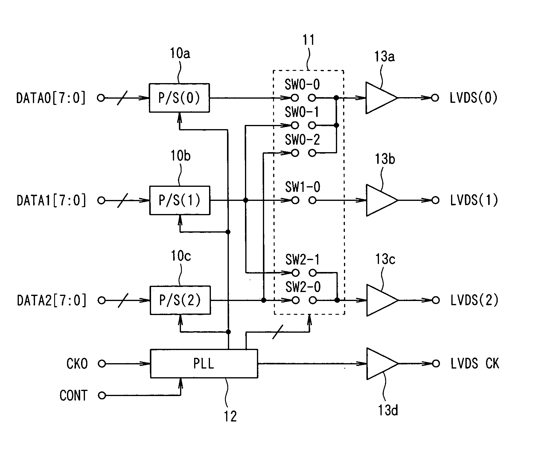
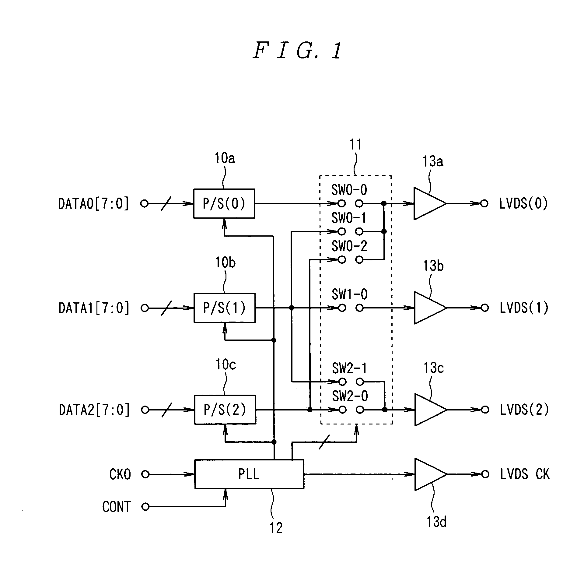
[0029]FIG. 1 is a block diagram showing an embodiment of a transmission-side circuit of an LVDS system of the present invention. As shown in FIG. 1, the transmission-side circuit of the LVDS system of this embodiment is constituted by including;

[0030] parallel / serial (P / S) conversion circuits 10a to 10c for respectively converting a parallel signal into a serial signal, a PLL (Phase Locked Loop) circuit 12 for outputting an LVDS clock obtained by multiplying a clock signal CK0 used as an input, drivers 13a to13d set correspondingly to the parallel...


PUM


Abstract

In an LVDS system for converting N types (for example N=3) of parallel signals into serial signals and sending/receiving the converted serial signals between a driver and a receiver through M (M≦N) signal lines, a sequencer 11 for selecting drivers 10a to 10c to be used in accordance with the number of signal lines used for transmission/reception and a reception-side sequencer for selecting a receiver to be used in accordance with the number of signal lines M used for transmission/reception are included to perform transmission/reception by using the driver and receiver selected by the both sequencers. Thus, it is possible to select the number of channels and a data rate optimum for the impedance of a signal line without fixing the number of signal lines used for transmission/reception.

Description

FIELD OF THE INVENTION [0001] The present invention relates to a serial transmission system such as a differential signal transmission system (Low Voltage Differential Signaling; hereafter referred to as LVDS), its transmission-side circuit, and its reception-side circuit, particularly to a system for converting a parallel signal of a plurality of bits into a serial signal, transmitting the signal, and returning the signal to the original parallel signal after receiving it and its transmission / reception circuit. BACKGROUND OF THE INVENTION [0002] When transmitting a pulse signal through an electrical wire, an LVDS system is known as a transmission method for preventing a signal error due to the influence of external noises on the electrical wire (for example, JP2002-237853A) In the case of this LVDS system, a transmission-side circuit transmits a pulse signal to be transmitted as two pulse signals of a positive phase (+side) and negative phase (−side) (that is, as a differential sig...

Claims


Application Information

Patent Timeline
Patent Type & Authority Applications(United States)
IPC IPC(8): H04B3/00G06F3/00H04L25/02
CPCH03K17/002
Inventor TAKEUCHI, SEIJI
Owner ASAHI KASEI ELECTRONICS CO LTD
Why Eureka
Try Eureka