Line concentrator, relay control method, relay control program, storage medium storing the relay control program, information processing device, dhcp server, dhcp processing method, dhcp processing program, storage medium storing the dhcp processing program and information processing system

a relay control and relay control technology, applied in the field of line concentrators, can solve the problems of inefficient use of image forming devices, stop the operations of the overall image output system, and concentration of job output requests to specific image forming devices, etc., to achieve rapid data processing, the determination process of the line concentrator is extremely simple, and the effect of rapid data transfer processing

Active Publication Date: 2007-04-12
SHARP KK
View PDF16 Cites 35 Cited by
  • Summary
  • Abstract
  • Description
  • Claims
  • Application Information

AI Technical Summary

Benefits of technology

[0017] Further, the line concentrator transfers received data to all of the information processing devices belonging to a group corresponding to a virtual address. Among the information processing devices having received the data, the information processing device which can process the received data fastest processes the received data. This solves the problems, such as concentration of jobs to a specific information processing device, and realizes a quick data proces...

Problems solved by technology

In such an image output system, however, it can be considered that there could occur concentration of job output requests to a specific image forming device.
This may cause inefficient use of the image forming devices.
However, the conventional image output system described above has the following problems: In the image output system disclosed in Patent Document 1, the printer server performs a centralized management of all the printers on the communications network.
In this arrangement, there is the problem that inoperable condition of the printer server for some reason stops the operations of the overall image output system.
This raises the problem of a long processing time between the instant when the ...

Method used


Image

  • Line concentrator, relay control method, relay control program, storage medium storing the relay control program, information processing device, dhcp server, dhcp processing method, dhcp processing program, storage medium storing the dhcp processing program and information processing system
  • Line concentrator, relay control method, relay control program, storage medium storing the relay control program, information processing device, dhcp server, dhcp processing method, dhcp processing program, storage medium storing the dhcp processing program and information processing system
  • Line concentrator, relay control method, relay control program, storage medium storing the relay control program, information processing device, dhcp server, dhcp processing method, dhcp processing program, storage medium storing the dhcp processing program and information processing system

Examples


Embodiment Construction

[0053] The following will describe one embodiment of the present invention with reference to FIGS. 1 through 18.

[0054] Structure of Image Output System

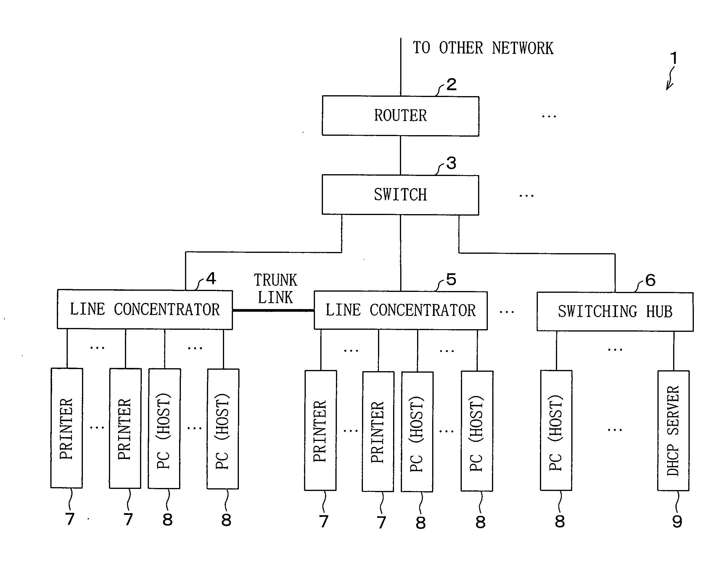
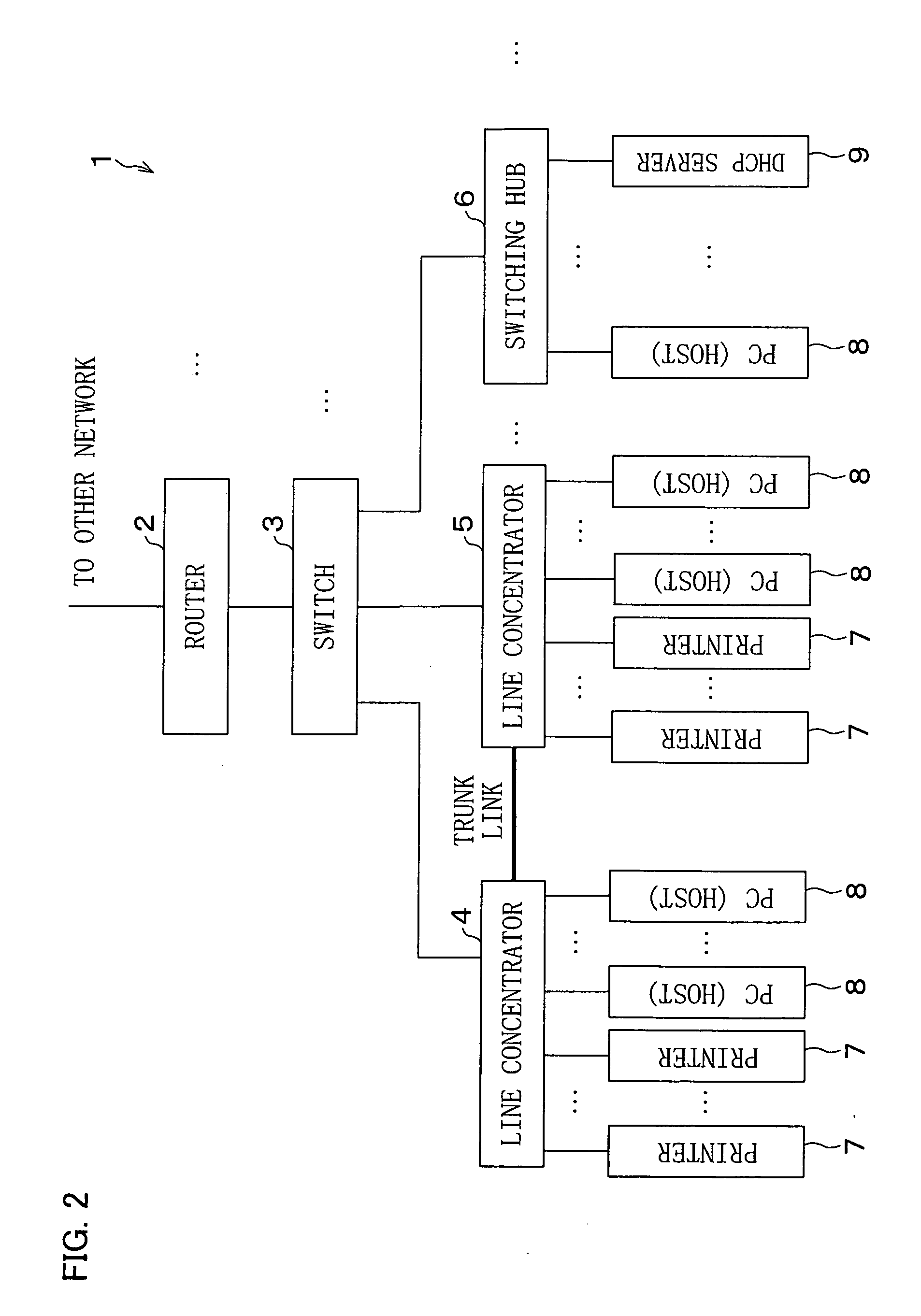
[0055]FIG. 2 is a block diagram schematically illustrating an image output system 1 as Structural Example 1 according to the present embodiment. As illustrated in FIG. 2, the image output system 1 is realized by a star topology LAN having a router 2 at its center.

[0056] Cooperating with a switch 3, the router 2 controls communications of line concentrators 4 and 5 and a switching hub 6, which are connected to the switch 3. Further, the router 2 has the function of enabling the connection between the image output system 1 and an external communications network (network).

[0057] Each of the line concentrators 4 and 5 is arranged so as to allow for a star connection between a plurality of printers 7 and a plurality of PCs (hosts) 8. The switching hub 6 is arranged so as to allow for a star connection between a plurality of PCs 8 and a...


PUM


Abstract

A line concentrator classifies printers connected via a communications network into groups according to the capabilities of the printers and includes a storage section which stores a VLAN table classifying the printers into groups and listing virtual addresses corresponding to the respective groups. When a monitoring section receives data addressed to a virtual address, it refers to the VLAN table and performs controls so as to transmit the received data to all of the printers belonging to the group corresponding to the virtual address. Thus, it is possible to eliminate the problem, such as concentration of jobs to a specific information processing device, and to provide a line concentrator capable of rapidly performing data transfer processing.

Description

TECHNICAL FIELD [0001] The present invention relates to a line concentrator, a relay control method, an information processing device, a DHCP server, and a DHCP processing method, all of which are provided in an information processing system, such as an image output system, where a plurality of external devices including, for example, a copier, a scanner, and an MFP (Multi Function Printer) are connected to one another via a network. BACKGROUND ART [0002] With improved performance and price-reduction of computers, the construction of a network system has been recently developed where peripheral equipments shared in a communications network such as LAN (Local Area Network) performs various operations under the instructions from computers. [0003] Peripheral devices shared in the communications network are, for example, a copier, a scanner, an image forming device such as MFP. Such a network system is constructed that a plurality of image forming devices are connected to each other ove...

Claims


Application Information

Patent Timeline
IPC IPC(8): H04L12/56H04L12/44G06F3/12H04L12/46
CPCH04L12/4641
Inventor UMEKAGE, ATSUSHITAKATANI, HIROSHIKUNIKAWA, NORIHIDE
Owner SHARP KK
Why Eureka
Try Eureka