Hollow needle for obturating dental cavities

a technology of hollow needles and hollow needles, which is applied in the field of hollow needles, can solve the problems of burdensome removal of hollow needles from the chamber of syringes

Inactive Publication Date: 2005-08-25
J MORITA USA
View PDF7 Cites 14 Cited by
  • Summary
  • Abstract
  • Description
  • Claims
  • Application Information

AI Technical Summary

Benefits of technology

[0004] In view of the foregoing, it is a feature of the present invention to eliminate the difficult procedure of cleaning a syringe housing a thermoplastic material that was formerly heated to a plastic state that has cooled down and adheres to the walls of the syringe. It is burdensome to remove this material from the ...

Problems solved by technology

It is burdensome to remove this m...

Method used


Image

  • Hollow needle for obturating dental cavities
  • Hollow needle for obturating dental cavities
  • Hollow needle for obturating dental cavities

Examples


Embodiment Construction

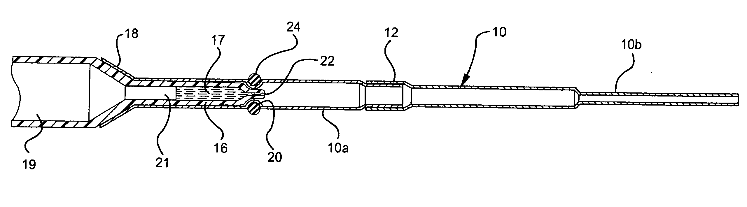
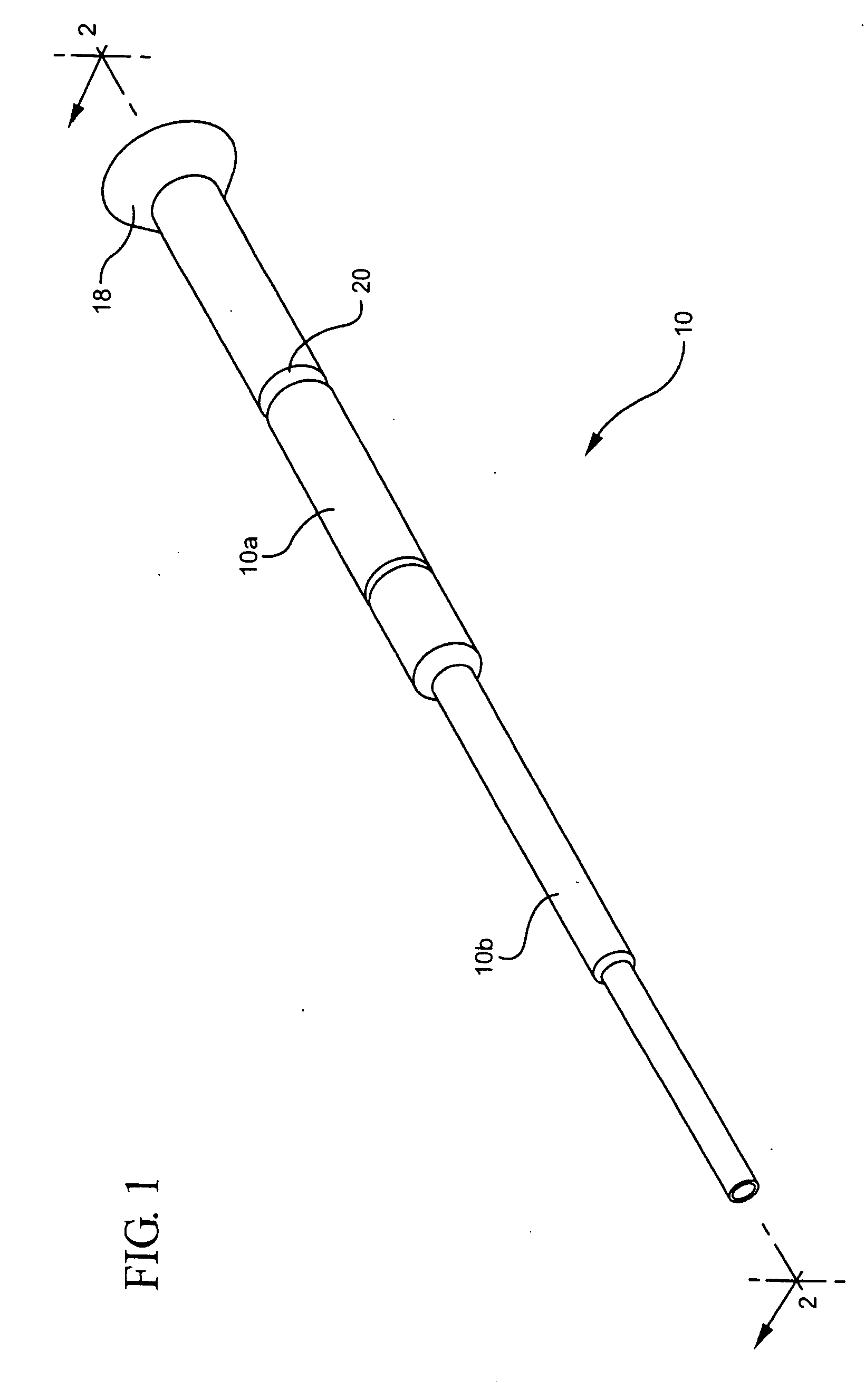
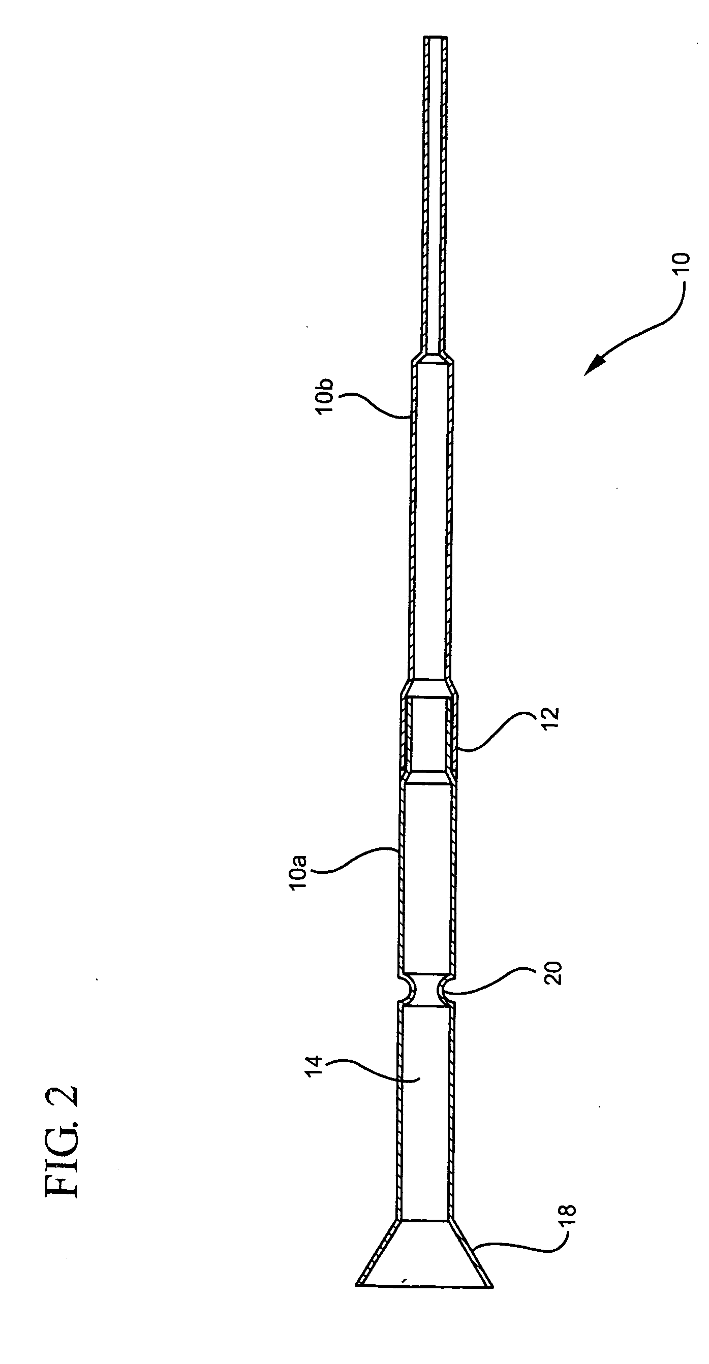
[0013] As seen in the drawings, the hollow needle for dental procedures is referred to generally by the reference numeral 10 and constitutes two parts, or sections 10a and 10b, which are connected together, for example by soldering, brazing or gluing. The connection of the two parts 10a and 10b is clearly seen at 12 in FIGS. 2 and 3 of the drawings. The working length of the needle can be increased by varying the length of part 10b prior to attachment to part 10a. Thus, the overall length of the needle can be selected by the dental professional in the order of 20 mm to 30 mm long depending upon the requirements for the particular procedure.

[0014] The back end of the needle, which is part 10a, has a larger diameter than the forward end, or part 10b. The back end of the needle is provided with a chamber 14 of a size to accommodate and house an open ended cartridge 16 for heated thermoplastic material, such as gutta perch, for filling a cavity of a tooth. The back end of the needle is...


PUM


Abstract

A two-part needle for a dental syringe in which the first part of the needle is attached to the syringe and has a larger cross0section than the other part, which is malleable, can be increased while the first part has a chamber for housing a cartridge with thermoplastic material therein that is caused to flow through the needle and into the dental cavity.

Description

[0001] The present invention is directed to a hollow needle in which the heated open-ended cartridge containing thermoplastic material, such as gutta-percha, is housed within a part of the needle and ejected into the dental cavity, for example, in a root canal procedure. [0002] The ejection device is normally an endodontic syringe having a means for forcing the gutta-percha, or other thermoplastic material from the cartridge and through the hollow needle to the root canal. The thermoplastic material is initially heated in the syringe by heating means therein. The ejection means can be a piston, which is driven into the cartridge material so the heated thermoplastic material is caused to flow-through the needle and into the dental cavity conforming to the configuration of the cavity, resulting in the obturation of the cavity. The ejection means may be manual or motor-driven. [0003] In the past, the heated thermoplastic material was contained in a cartridge housed in the syringe as pa...

Claims


Application Information

Patent Timeline
IPC IPC(8): A61C5/04A61C5/06
CPCA61C5/062A61C5/04A61C5/50A61C5/62
Inventor EAGLE, ALDO
Owner J MORITA USA
Why Eureka
Try Eureka