
Exercise system using exercise resistance cables

Active Publication Date: 2005-08-25
VQ ACTIONCARE
View PDF46 Cites 25 Cited by
  • Summary
  • Abstract
  • Description
  • Claims
  • Application Information

AI Technical Summary

Benefits of technology

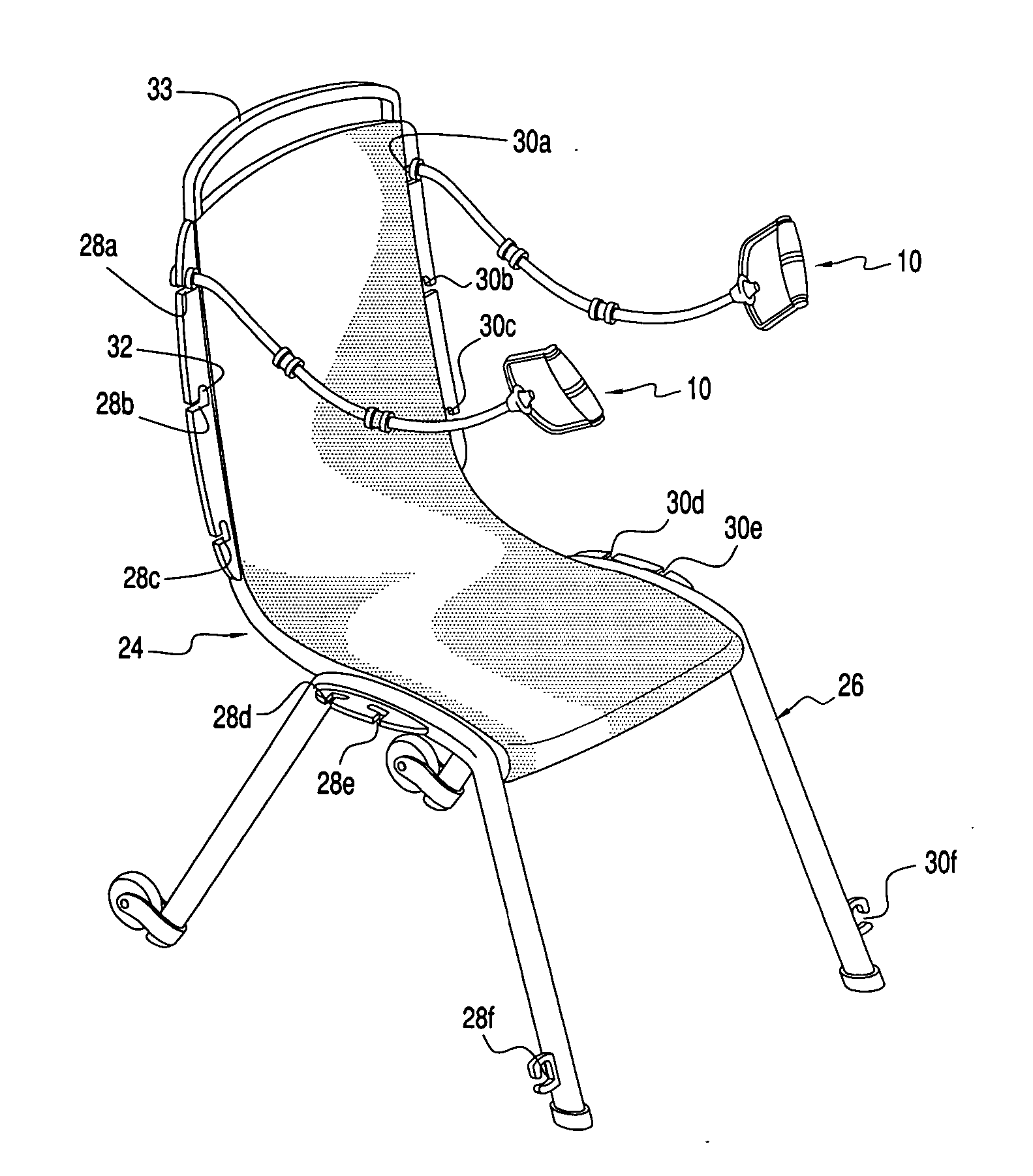
[0022] The systems of the present invention are particularly advantageous for use with elderly persons. The present invention is easy to use, particularly for the elderly, because, assuming that the chairs are set up, the person merely picks up the desired cables and brings those cables to his or her workout station, attaches the cable(s) and is ready to work out.
[0024] The present exercise system provides strength training without the stress of a pre-designed rigid machine. A person can take cables, connect them to the anchor assembly and exercise in accordance with his body height and size.
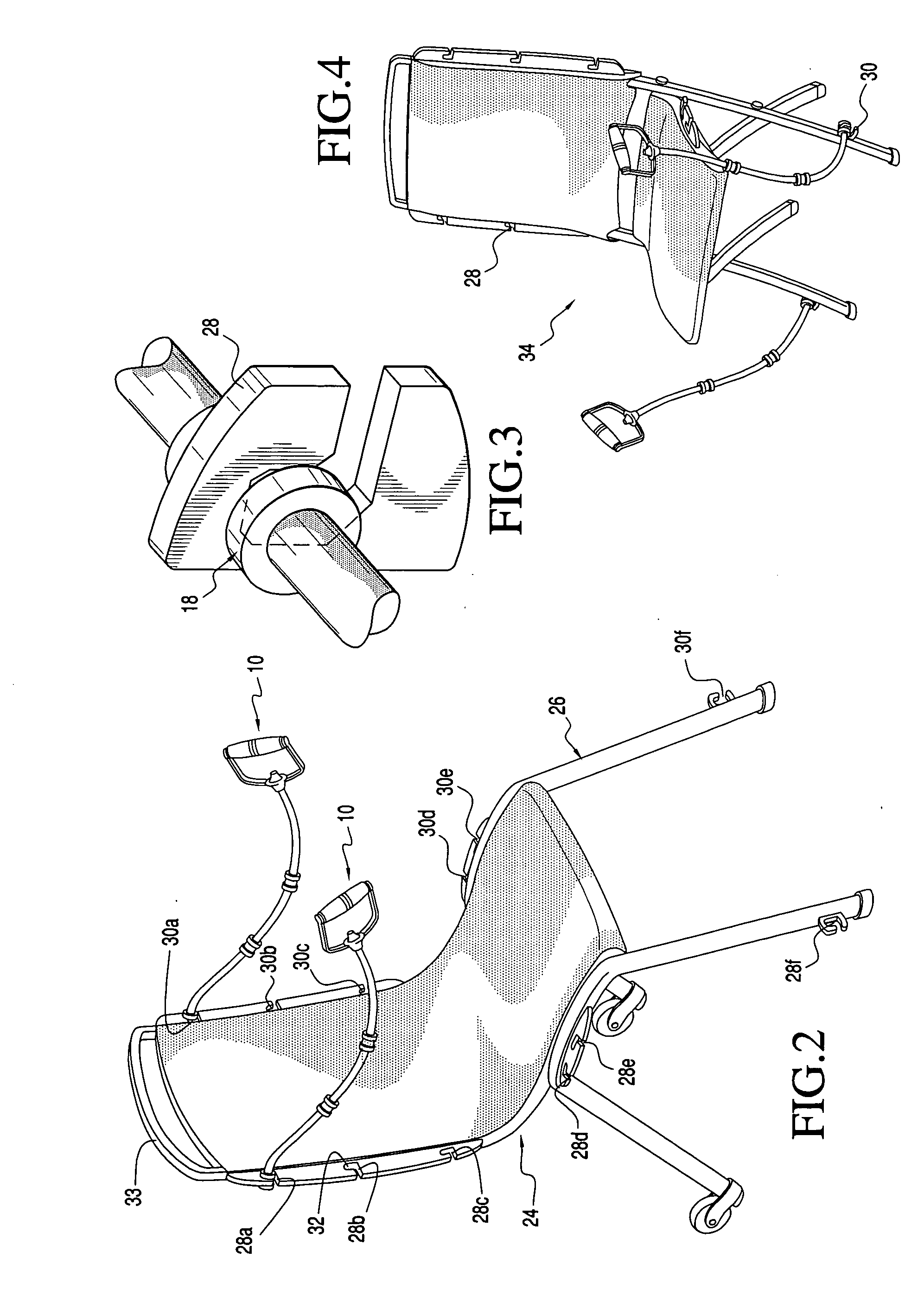
[0026] Use of the present invention has several advantages over the prior art. It allows the user to easily change resistance levels and adjust resistant lengths—all from a seated position. The present inventive concepts provide safe, low impact exercise solutions that are easy to use and make the user feel better. The folding resistance chair provides a very convenient home exercise system. The chair allows the user to perform a full body workout from a safe, comfortable seated position. When seated, balance and stability is maintained as the arms, chest, shoulders, abdomen, back, and legs are exercised. The anchor assemblies ensure that the cable remains at the best angle for each exercise. The unique cable system offers a wide range of upper body and lower body exercises and provides resistance without use of heavy weights. When utilizing the resistance cables with the resistance chair, the user is provided with a safe, comfortable, secure and well rounded exercise routine.

Problems solved by technology

As in the other patents, discussed above, the Farran system is somewhat complicated.
Furthermore, it is non-mobile and is limited in the amount of workout routines allotted.
A mobile / moving system is not generally preferred for use with the elderly and is somewhat complicated.
Positioning of the swinging arms requires time and labor.

Method used


Image

  • Exercise system using exercise resistance cables
  • Exercise system using exercise resistance cables
  • Exercise system using exercise resistance cables

Examples


Embodiment Construction

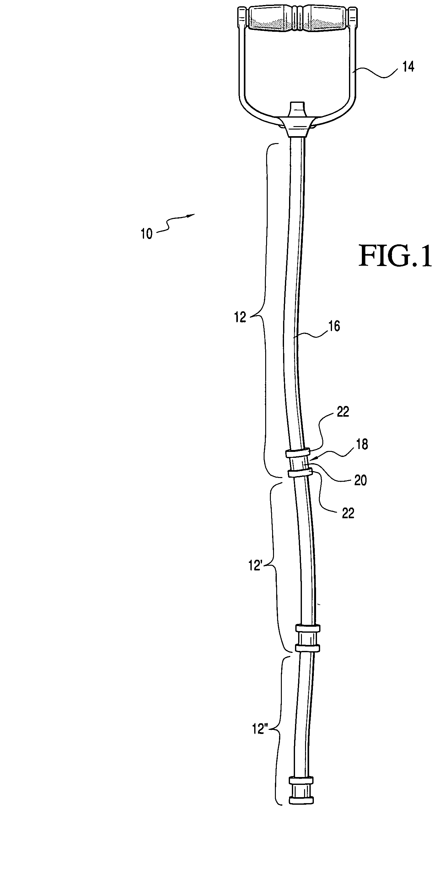
[0040] Referring now to the drawings and the characters of reference marked thereon, FIG. 1 illustrates a first embodiment of the exercise resistance cable apparatus of the present invention, designated generally as 10. The exercise resistance cable apparatus 10 includes a first cable / anchor module 12 and a handgrip 14. Additional cable / anchor modules 12′, 12″ are connected to the first cable / anchor module 12. The cable / anchor modules 12 are serially connected to provide a desired user length and resistance.

[0041] Each cable / anchor module 12 includes an elastic exercise resistance cable 16 which is connected at an end thereof to a cable expansion anchor 18. Each cable expansion anchor 18 is preferably spool-shaped and includes a shaft 20 and two longitudinally spaced radially extending flanges 22.

[0042] The additional cable / anchor modules 12′, 12″, . . . 12n are connected to provide the correct user length and resistance commensurate with the user's strength. Generally, the resist...


PUM


Abstract

An exercise resistance cable apparatus for engagement with a pulley assembly of a support structure and with a cable locking pin of an anchor assembly of the support structure. The exercise resistance cable apparatus includes an elastic exercise resistance cable. A cable anchor ring is securely connected to a first end of the elastic exercise resistance cable. A handgrip is connected to a second end of the elastic exercise resistance cable. During use the elastic exercise resistance cable is directed through an activity bay of the pulley assembly and ultimately attached, via the cable anchor ring, to the cable locking pin of the anchor assembly of the support structure. The exercise resistance cable apparatus is particularly adapted to be used with an exercise chair having a frame with pulley assemblies defining a plurality of activity bays positioned at desired locations thereon.

Description

CROSS REFERENCE TO RELATED APPLICATION [0001] This is a continuation-in-part of U.S. Ser. No. 10 / 783,532, entitled “Exercise System Using Exercise Resistance Cables”, filed Feb. 21, 2004.BACKGROUND OF THE INVENTION [0002] 1. Field of the Invention [0003] The present invention relates to exercise devices and systems and more particularly to an exercise system that utilizes removable exercise resistance cables that connect to activity bays of a support structure. [0004] 2. Description of the Related Art [0005] The use of resistance cables for exercising is well known in the prior art. There are a multitude of different exercise systems and devices that have been previously disclosed or are currently in the market to supply the increasing demand for physical fitness. Many of these utilize resistance cables. For example, as far back as 1902, U.S. Pat. No. 704,840, issued to J. C. Korth et disclosed the use of an exercising machine employing elastic cords. U.S. Pat. No. 3,606,321, issued...

Claims


Application Information

Patent Timeline
IPC IPC(8): A63B21/02A63B21/04A63B21/055A63B21/062A63B21/16A63B23/12
CPCA63B21/00061A63B2022/0652A63B21/04A63B21/0442A63B21/055A63B21/0552A63B21/0557A63B21/1484A63B21/154A63B22/0012A63B22/0056A63B22/0605A63B22/0694A63B23/03516A63B23/0476A63B23/12A63B23/1245A63B2021/1609A63B2021/1672A63B2023/006A63B2071/025A63B2208/0233A63B2208/0252A63B2225/10A63B22/0002A63B22/0046A63B21/00069A63B21/4043A63B21/1609A63B21/1672A63B23/1209A63B23/03541A63B21/4035
Inventor BOWSER, JOHN
Owner VQ ACTIONCARE
Learn More