
Method for determining a rotor position of a synchronous motor

a synchronous motor and rotor position technology, applied in the direction of motor/generator/converter stopper, dynamo-electric gear control, motor/generator/converter stopper, etc., can solve the problem of the absolute value of the current vector and the inability to adequately determine the position of the motor, so as to achieve the effect of reducing the computing tim

Active Publication Date: 2005-08-25
SIEMENS AG
View PDF3 Cites 7 Cited by
  • Summary
  • Abstract
  • Description
  • Claims
  • Application Information

AI Technical Summary

Benefits of technology

[0010] According to still another advantageous feature of the invention, the Fourier coefficients of the first harmonic of the inverse values can be determined by digitally filtering only the inverse values that are in a range where the excursion of the rotor is negative. Alternatively, the Fourier coefficients of the first harmonic of the inverse values can be determined by digitally filtering several inverse values only in a range where the excursion of the rotor is positive. These approaches minimize the computing time as compared to an evaluation process that includes all the inverse values.

Problems solved by technology

However, the curve describing the absolute value of the current vectors is very flat particularly in the vicinity of the minimum absolute values of the current vectors and the measured values have superimposed disturbances in practical applications.
As a consequence, the motor position cannot be adequately determined.

Method used


Image

  • Method for determining a rotor position of a synchronous motor
  • Method for determining a rotor position of a synchronous motor
  • Method for determining a rotor position of a synchronous motor

Examples


Embodiment Construction

[0019] Throughout all the Figures, same or corresponding elements are generally indicated by same reference numerals. These depicted embodiments are to be understood as illustrative of the invention and not as limiting in any way. It should also be understood that the drawings are not necessarily to scale and that the embodiments are sometimes illustrated by graphic symbols, phantom lines, diagrammatic representations and fragmentary views. In certain instances, details which are not necessary for an understanding of the present invention or which render other details difficult to perceive may have been omitted.

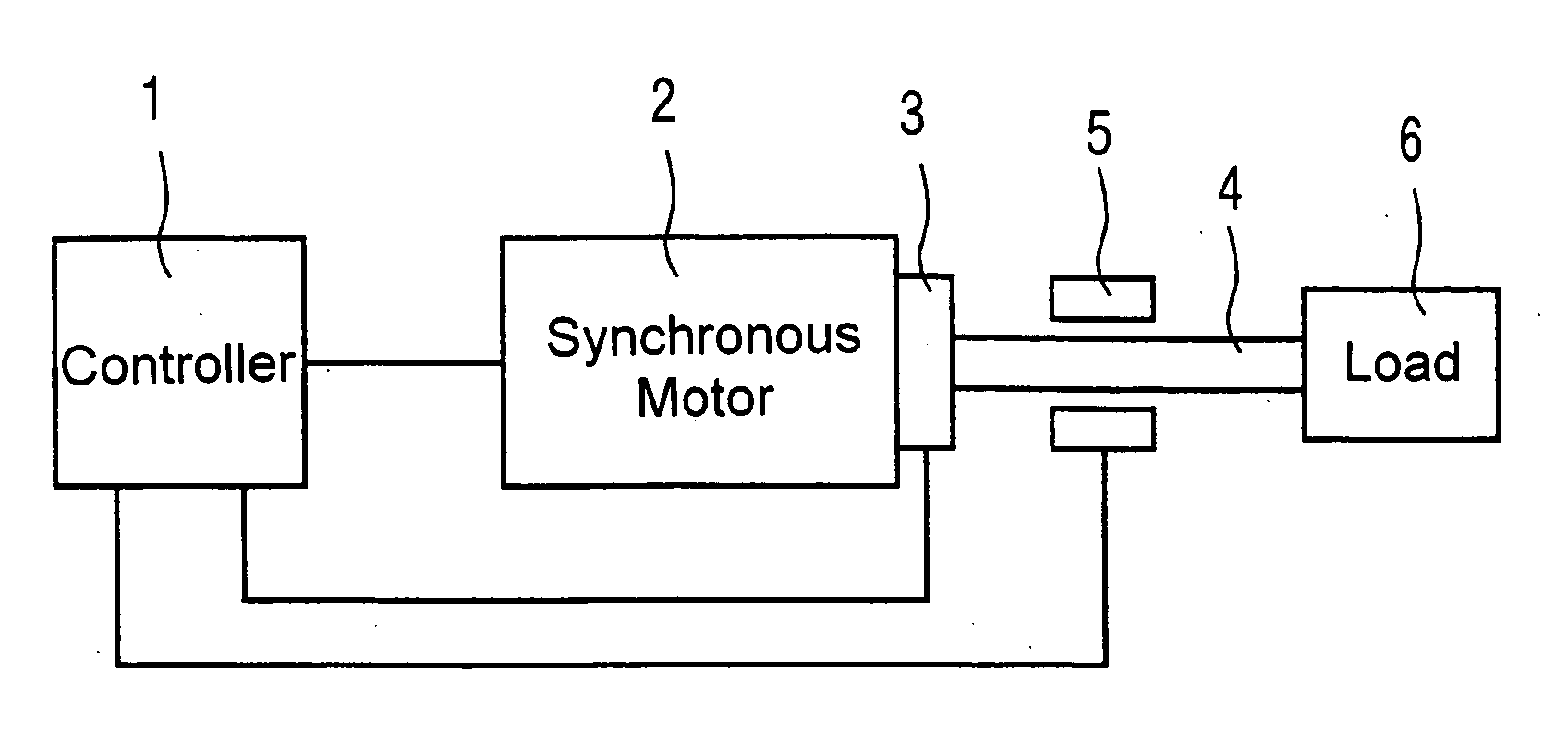
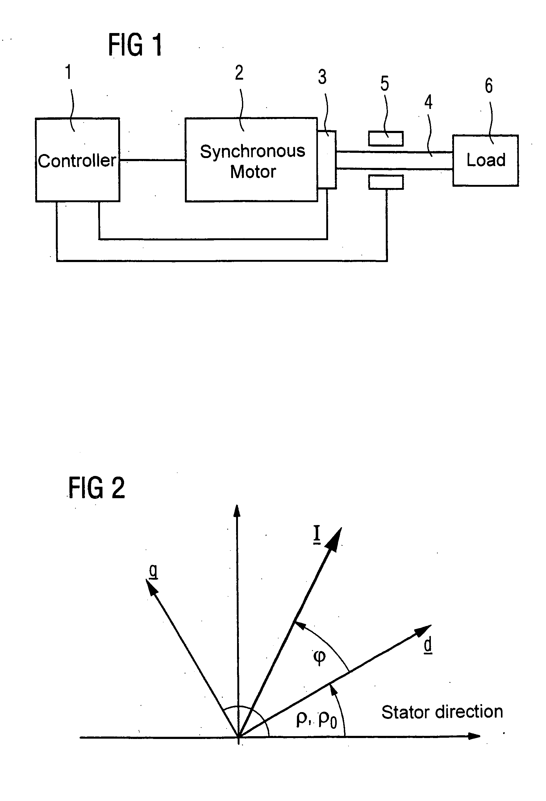
[0020] Turning now to the drawing, and in particular to FIG. 1, there is shown a block diagram of a drive unit with a synchronous motor 2, which is controlled by a controller 1. The rotor position of the synchronous motor 2, which in the illustrated exemplary embodiment is defined as a rotor position angle ρ, is measured by a position measuring device 3. The position measuri...


PUM


Abstract

In a method for determining the rotor position of a synchronous motor, a plurality of current vectors having different directions is applied to the synchronous motor. Absolute values of required ones of the current vectors are determined to obtain a defined excursion of the rotor. Inverse values of the determined current vectors are then digitally filtered using several of the inverse values to determine Fourier coefficients of the first harmonic of the inverse values. The rotor position of the synchronous motor can then accurately be computed with the determined Fourier coefficients.

Description

CROSS-REFERENCES TO RELATED APPLICATIONS [0001] This application claims the priority of German Patent Application, Ser. No. 10 2004 008 250.2, filed Feb. 19, 2004, pursuant to 35 U.S.C. 119(a)-(d), the disclosure of which is incorporated herein by reference. BACKGROUND OF THE INVENTION [0002] The present invention relates to a method for determining a rotor position of a synchronous motor. The present invention also relates to a data carrier with a computer program stored thereon for performing method, as well as to a computer with a program memory for storing the computer program. The present invention further relates to a machine-tool or production machine with the computer, wherein the computer can be implemented as a controller. In the following description, the term “production machine” is used in a generic sense and also includes robots which generally follow the concepts outlined here. [0003] Several conventional methods are known for determining the position of a rotor of a ...

Claims


Application Information

Patent Timeline
Patent Type & Authority Applications(United States)
IPC IPC(8): G01C19/00H02P6/20H02P21/00
CPCH02P25/021H02P21/0035H02P21/22H02P25/024
Inventor NEMETH-CSOKA, MIHALYKUNZEL, STEFAN
Owner SIEMENS AG
Learn More