
Centralized network configuration entity and time sensitive network control system comprising same

A network configuration and sensitive network technology, applied in time-division multiplexing systems, transmission systems, electrical components, etc., can solve problems such as unsatisfactory delays, undisclosed control technologies, etc., and achieve the effect of minimizing calculation time

Pending Publication Date: 2022-07-29
IUCF HYU (IND UNIV COOP FOUNDATION HANYANG UNIV)
View PDF1 Cites 1 Cited by
  • Summary
  • Abstract
  • Description
  • Claims
  • Application Information

AI Technical Summary

Problems solved by technology

[0007] However, no control technique is disclosed in conventional network systems that allows time-sensitive data to arrive at a receiving entity within a required delay in an environment where time-insensitive data and time-sensitive data coexist.
In other words, conventional network systems cannot meet the required delay while controlling data traffic in an environment where only time-sensitive data is configured or time-sensitive and time-insensitive data are mixed

Method used


Image

  • Centralized network configuration entity and time sensitive network control system comprising same
  • Centralized network configuration entity and time sensitive network control system comprising same
  • Centralized network configuration entity and time sensitive network control system comprising same

Examples


Embodiment Construction

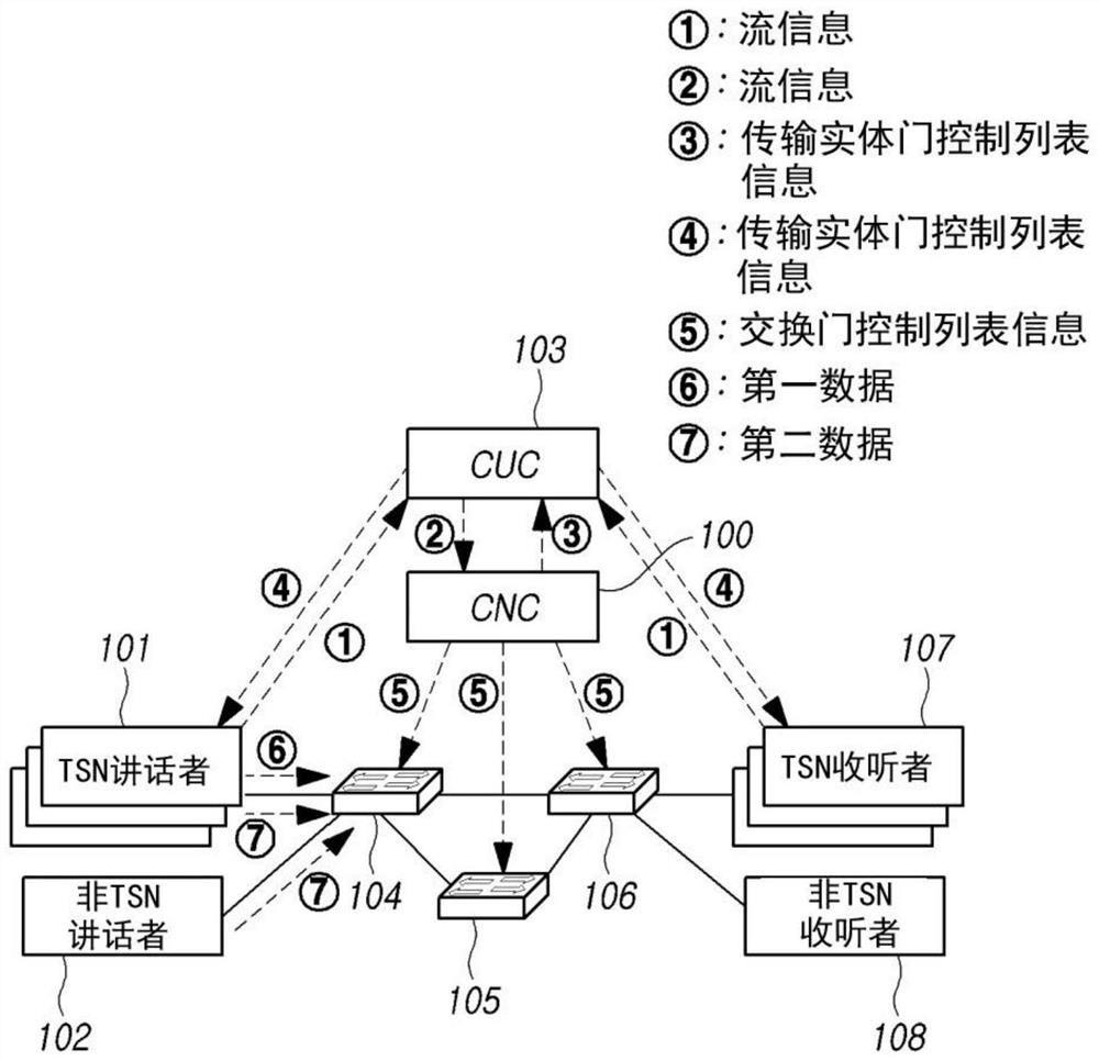
[0032] Hereinafter, embodiments of the present disclosure will be described in detail with reference to the accompanying drawings. The same or substantially the same reference numbers are used throughout the specification and throughout the drawings to refer to the same or substantially the same elements. Details of known techniques or functions may be skipped when deemed to obscure the subject matter of the present invention. When used in this specification, the terms "comprising" or "having" designate a stated feature, region, integer, step, operation, element and / or component, but do not exclude one or more other features, regions, integers , steps, operations, elements, components and / or the presence or addition of groups of them. As used herein, an article in the singular is intended to include the plural as well, unless the context clearly dictates otherwise.

[0033] Expressions such as "first," "second," "A," "B," "(a)," and "(b)" may be used to describe components o...


PUM


Abstract

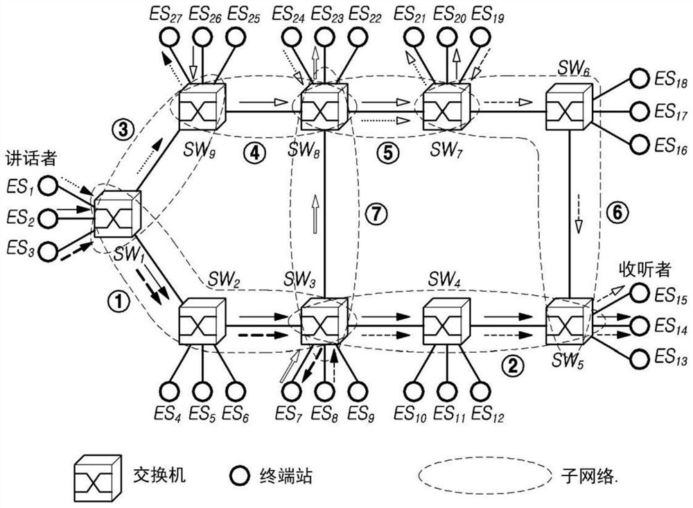
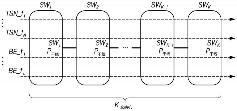
The embodiment of the invention relates to a time-sensitive network control system and a centralized network configuration entity for controlling data traffic in the time-sensitive network control system. In one aspect, embodiments of the present application may provide a centralized network configuration entity for controlling data traffic scheduling of a time-sensitive network, the entity comprising: a receiving unit for receiving flow information about a plurality of traffic flows from a centralized user configuration entity, the plurality of traffic flows are used for transmitting first data sensitive to a time delay in a sub-network and second data insensitive to the time delay; a resource allocation unit that uses the flow information to allocate output port time resources of respective switching entities included in the sub-network, the respective switching entities being used to transmit the first data and the second data; a gate control list generation unit for generating switching gate control list information for controlling the operation of the switching entity and / or sending entity gate control list information for controlling the operation of the switching entity on the basis of the stream information and the output port time resource, and / or sending entity gate control list information for controlling the operation of the switching entity on the basis of the stream information and the output port time resource. The sending entity gate control list information is used for controlling data transmission gates of a plurality of sending entities sending the plurality of traffic flows; and the sending unit is used for sending the switching gate control list information to the switch and sending entity gate control list information to the centralized user configuration entity.

Description

[0001] CROSS-REFERENCE TO RELATED APPLICATIONS [0002] This patent application claims priority under 35 U.S.C. 119(a) to Korean Patent Application No. 10-2019-0127845, filed with the Korean Intellectual Property Office on October 15, 2019, the disclosure of which is incorporated herein by reference in its entirety . This patent application claims priority to other applications filed in other countries, the disclosures of which are also incorporated herein by reference in their entirety. technical field [0003] Embodiments of the present application relate to a time-sensitive network control system and a central network configurator that controls data traffic in the time-sensitive network control system. Background technique [0004] Ultra-low latency infrastructure technology (Ultra-low latency infrastructure technology) is a technology for real-time time-sensitive communication and industrial process control measurement information exchange that goes beyond the Internet...

Claims


Application Information

Patent Timeline
Patent Type & Authority Applications(China)
IPC IPC(8): H04L47/56H04L47/2441H04L49/112H04J3/16
CPCH04L47/56H04L47/283H04L47/781H04L47/826H04J3/1682H04L47/625
Inventor 洪承镐李玉庭
Owner IUCF HYU (IND UNIV COOP FOUNDATION HANYANG UNIV)
Learn More