Insulated stud panel and mehod of making such

Inactive Publication Date: 2005-09-01
HAGEN JR HANS T +2
View PDF64 Cites 99 Cited by
  • Summary
  • Abstract
  • Description
  • Claims
  • Application Information

AI Technical Summary

Benefits of technology

[0027] Another advantage of the present invention is an efficient use of materials. Insulation, normally providing only an insulative attribute, provides a structural attribute (without being structural insulation per se) when insulation in adjacent inner regions of the stud panel communicate such that insulation throughout the stud panel is tied together and is essentially one-piece and integral. A feature contributing to this advantage is the thermal break provided by the studs that terminate short of one of the exterior or interior sheathing. Another feature contributing to this advantage is the hole or set of holes formed in the inner studs and through which insulation extends.
[0028] Another advantage of the present invention is that such tied together insulation foam is of a relatively low density. Low density foam is not normally considered to be structural foam. However, here, by filling up all possible spaces and by further tying foam together from adjacent inner regions defined by studs, such low density foam provides strength and support.
[0029] Another advantage of the present invention is a stud panel having a greater R-value. A feature contributing to this advantage is the introduction of insulation to substantially all of the inner regions of the stud panel. Another feature contributing to this advantage is the retainer, su

Problems solved by technology

One problem relates to scarfing.
Scarfing is an undesirable job in the housing industry because it consumes a great amount of time, provides merely a rough or coarse trim, wastes insulation, requires the user to find land fills that accept insulation waste, and then requires the user to actually transport the waste material

Method used


Image

  • Insulated stud panel and mehod of making such
  • Insulated stud panel and mehod of making such
  • Insulated stud panel and mehod of making such

Examples


Example

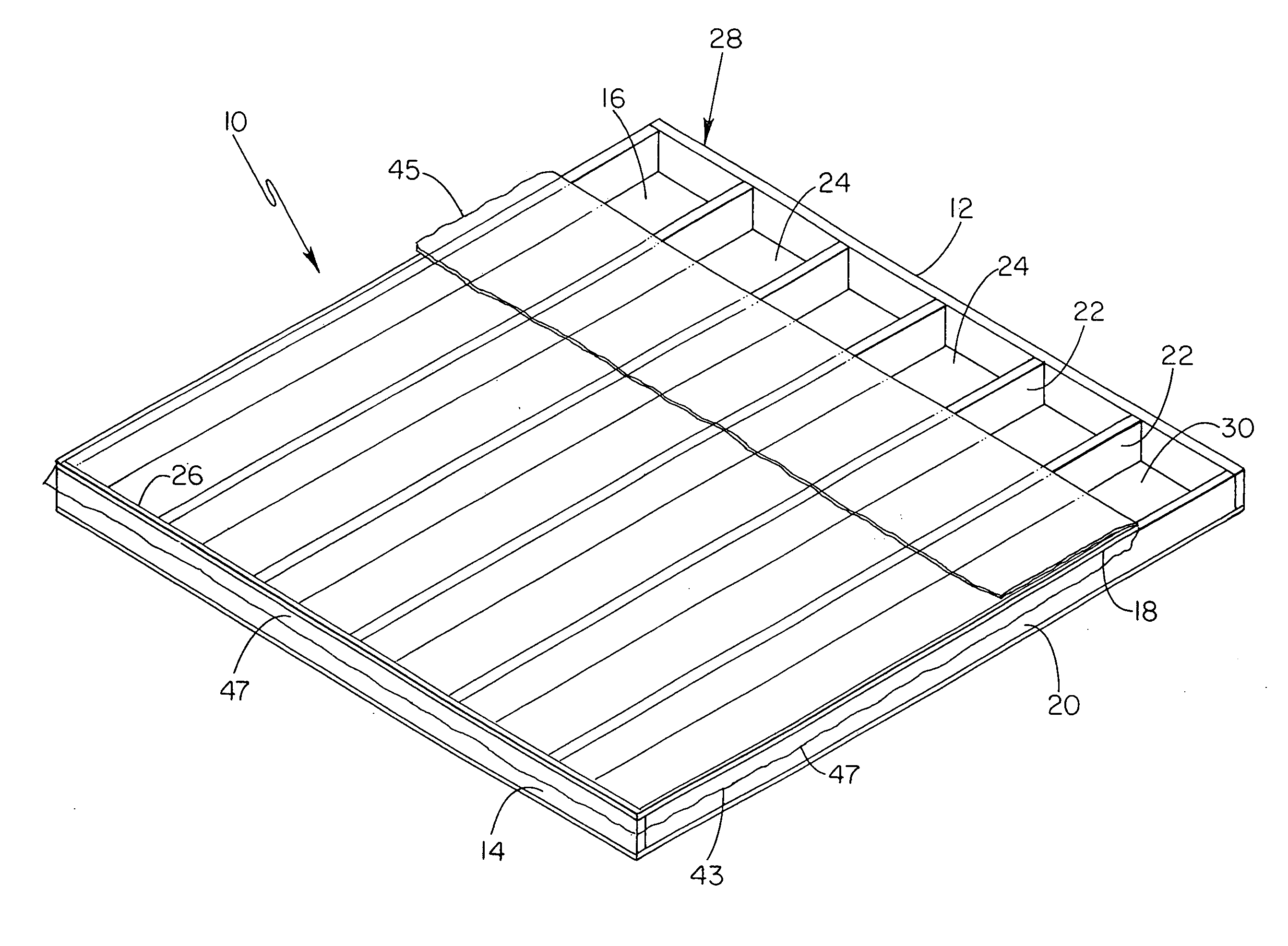
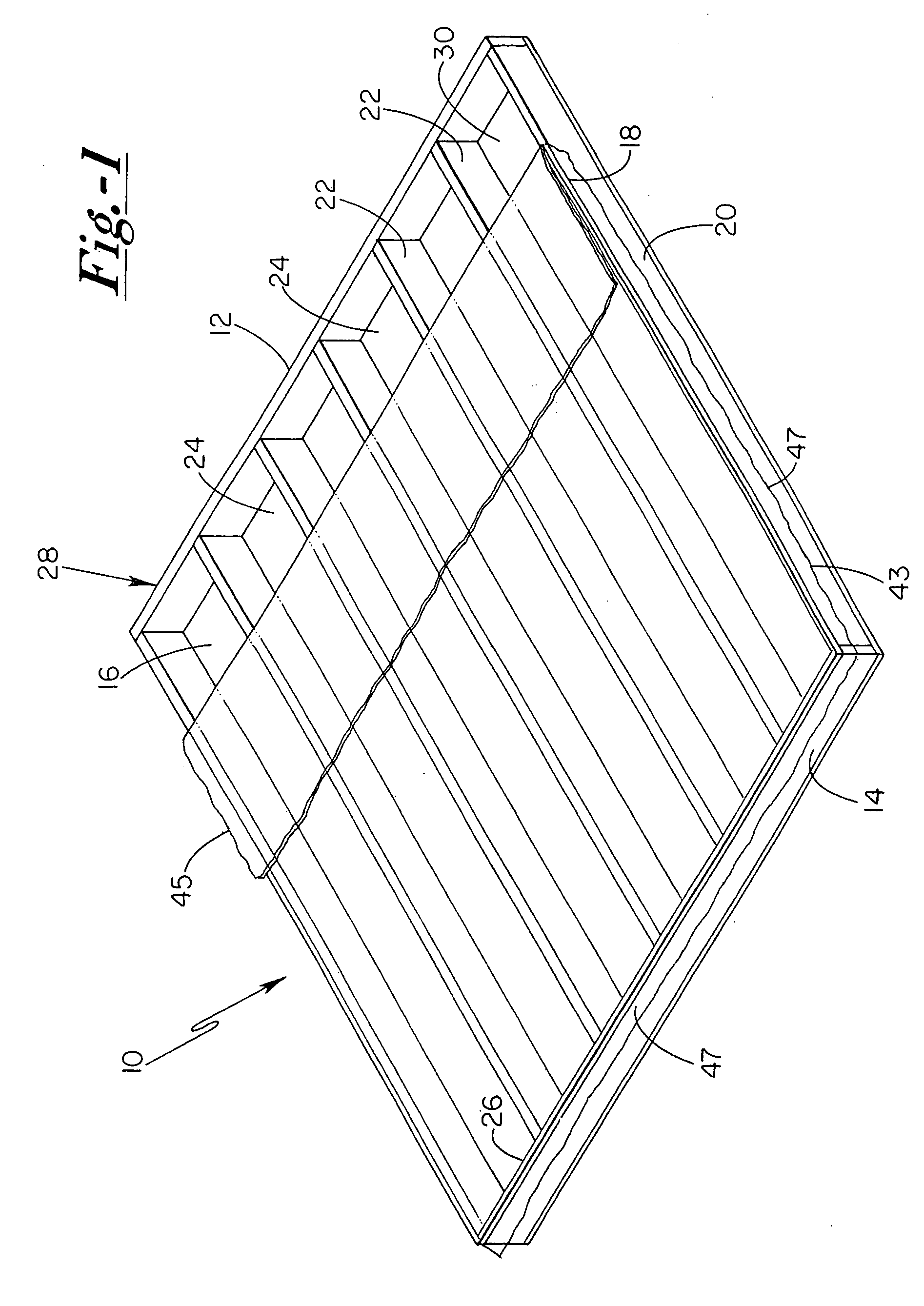
[0068]FIG. 1 shows a stud panel 10 of the present invention. Stud panel 10 includes a first, top (or bottom) plate 12, a second, bottom (or top) plate 14, exterior (or interior) sheathing 16, interior (or exterior) sheathing 18, a pair of end or outer studs 20, and a set of interior or inner studs 22, where studs 20 and 22 are between the first and second plates 12, 14 and further between the exterior and interior sheathing 16, 18. The stud panel 10 includes a set of inner regions or spaces 24, where each of the inner regions 24 is defined by inner faces of the first and second plate 12, 14, inner faces of the exterior and interior sheathing 16, 18, and inner faces of adjacent studs, where such adjacent studs are a combination of an outer stud and inner stud or a combination of two inner studs. Each of the inner regions 24, in the panel of FIG. 1, includes a closed end 26, into which insulation can be first introduced, and an open end 28, into which insulation can be introduced as a...


PUM

PropertyMeasurementUnit
Densityaaaaaaaaaa
Widthaaaaaaaaaa

Abstract

A stud panel and method of making a stud panel where interior sheathing may be a temporary piece of transparent plastic or a permanent panel of sheet rock so as to retain insulation in place and minimize scarfing. The stud panel may include studs having through holes extending in a length direction of the stud panel such that insulation in adjacent inner regions separated by such studs interlock with each other and contribute to a structural integrity of the stud panel. The stud panel may include a space between inner studs and one of the exterior and interior sheathing so as to provide a thermal and sound break between the exterior and inner sheathing so as to minimize heat, air and sound transfer between the exterior and interior sheathing. A method of making the stud panel is further disclosed, where such a method may include the step of incrementally introducing insulation from a closed end of an inner region to an open end of an inner region and may further include the step of automatically introducing insulation into the inner regions of the stud panel.

Description

[0001] This application claims the benefit under 35 U.S.C. 120 of U.S. patent application Ser. No. 10 / 860,882 filed Jun. 4, 2004, which claims priority under 35 U.S.C. 119(e) to U.S. Provisional Patent Application No. 60 / 476,774 filed Jun. 6, 2003. Each of these applications, i.e., U.S. patent application Ser. No. 10 / 860,882 and U.S. Provisional Patent Application No. 60 / 476,774, is hereby incorporated by reference in its entirety into this application.FIELD OF THE INVENTION [0002] The present invention relates generally to a stud panel, more particularly to an insulated stud panel, and specifically to a prefabricated insulated stud panel. BACKGROUND OF THE INVENTION [0003] Features of the present invention provide solutions to a number of problems now found in the housing industry. One problem relates to scarfing. “To scarf” means to trim or to cut off excess material. Scarfing, in the housing industry, means to trim or cut off insulation which protrudes from or has expanded outsid...

Claims


Application Information

Patent Timeline
IPC IPC(8): E04B1/74E04B1/76E04B2/70
CPCB29C44/186E04B1/7604E04F21/085E04B2001/743E04C2/386E04B2/707Y02A30/244
Inventor HAGEN, HANS T. JR.
Owner HAGEN JR HANS T
Why Eureka
Try Eureka