Magneto-rheological hydraulic power steering system

Inactive Publication Date: 2005-09-01
GM GLOBAL TECH OPERATIONS LLC
View PDF15 Cites 27 Cited by
  • Summary
  • Abstract
  • Description
  • Claims
  • Application Information

AI Technical Summary

Benefits of technology

[0009] One advantage of the present invention is that a magneto-rheological hydraulic power steering system is provided for a vehicle. Another advantage of the present invention is that the magneto-rheological hydraulic power steering system adopts direct control of the speed of the hydraulic power steering pump by using a magneto-rheological fluid (MRF) coupling integrated between the accessory drive shaft and the hydraulic power steering pump. Yet another advantage of the present invention is that the magneto-rheological hydraulic power steering system provides continuously adjustable speed by controlling the torque transmitted from the drive shaft to that of the power steering pump. Still another advantage of the present invention is that the magneto-rheological hydraulic power steering system improves vehicle fuel efficiency due to elimination of losses resulting from double energy conversion in a conventional electro-hydraulic power steering system.
[0010] A further advantage of the present invention is that the magneto-rheological hydraulic power steering system reduces cost due to a relatively simple low current controller replacing the costly high-current power-electronics of a conventional electro-hydraulic power steering system. Yet a further advantage of the present invention is that the magneto-rheological hydraulic power steering system provides variable power steering assist by controlling the pump speed of the hydraulic power steering system. Still a further advantage of the present invention is that the magneto-rheological hydraulic power steering system has redu

Problems solved by technology

Since the power steering pump is driven directly by the engine using a belt, its speed is determined by that of the engine and it operates continuously as long as the engine is running, resulting in continuous losses due to constant circulation of the hydraulic fluid through the steering gear.
This results in increased fuel consumption due to continuous operation of the power steering pump at speeds dictated by the engine speed, even when no steering assist is required.
In addition, the power steering pump has to provide the required flow and pressure for the worst case engine speed, which could be near idle, under static steering conditions, contrib

Method used


Image

  • Magneto-rheological hydraulic power steering system
  • Magneto-rheological hydraulic power steering system
  • Magneto-rheological hydraulic power steering system

Examples


Embodiment Construction

)

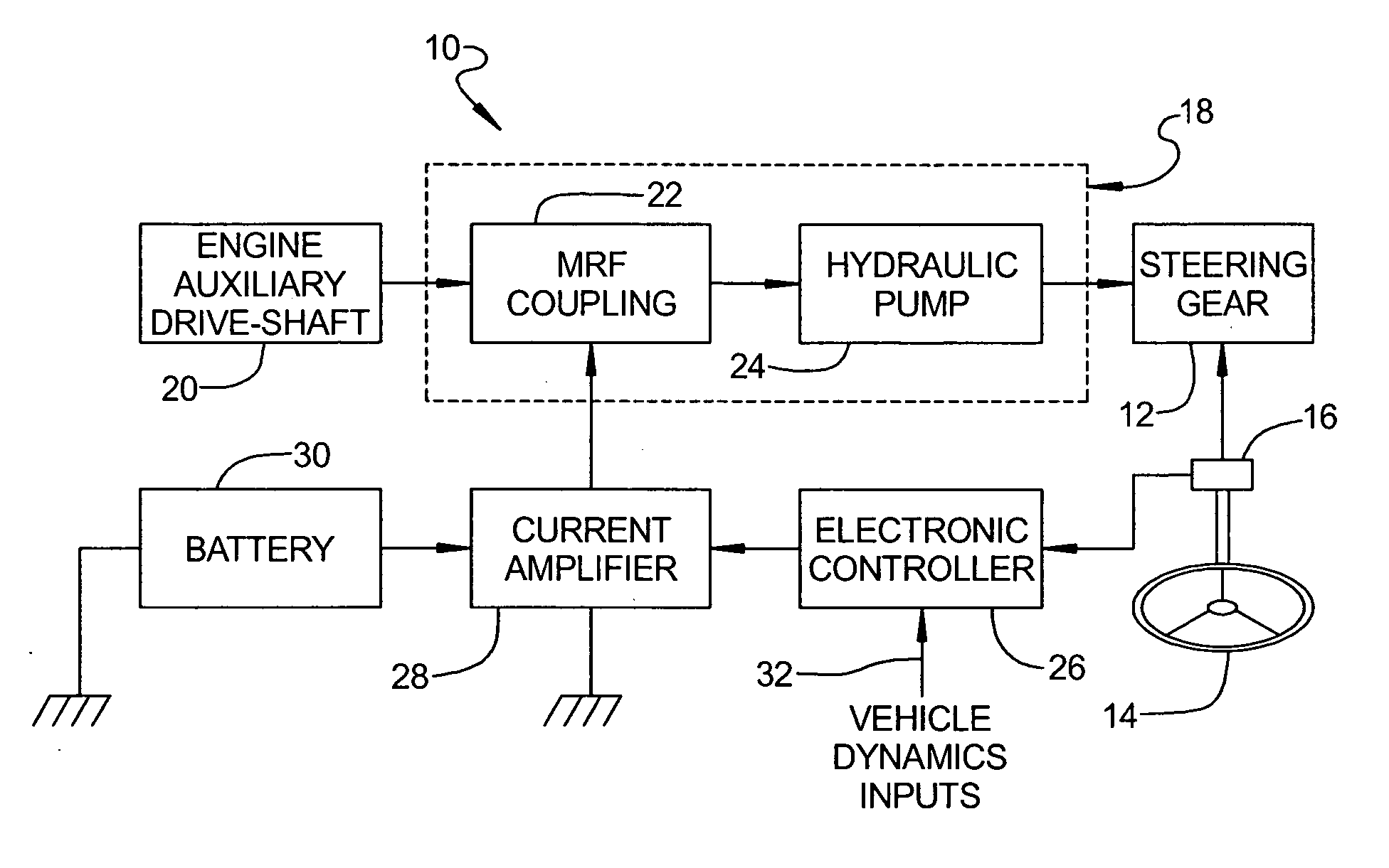
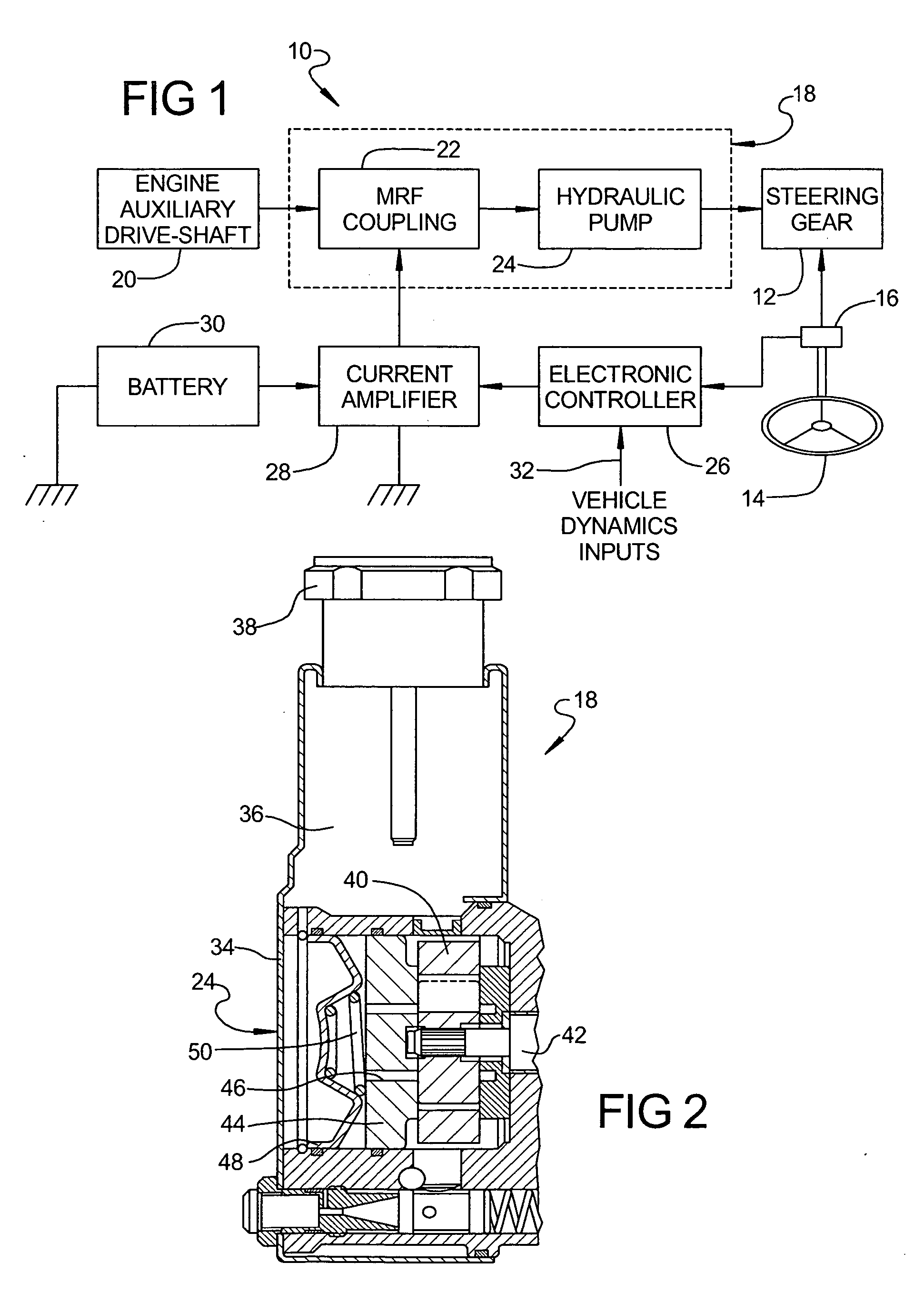
[0019] Referring to the drawings and in particular FIG. 1, one embodiment of a magneto-rheological hydraulic power steering system 10, according to the present invention, is shown for a vehicle (not shown) such as a motor vehicle or automotive vehicle. The magneto-rheological hydraulic power steering system 10 includes a steering gear 12 and a steering wheel 14 operatively connected to the steering gear 12. The magneto-rheological hydraulic power steering system 10 also includes at least one steering wheel sensor 16 operatively connected to the steering wheel 14 to sense angle and / or torque of the steering wheel 14. It should be appreciated that the steering gear 12, steering wheel 14, and steering wheel sensor 16 are conventional and known in the art.

[0020] The magneto-rheological hydraulic power steering system 10 includes a magneto-electrohydraulic power steering pump, generally indicated at 18 operatively connected to the power steering gear 12 and a drive-shaft such as an aux...


PUM


Abstract

A magneto-rheological hydraulic power steering system for a vehicle includes a magneto-rheological power steering pump interconnecting a power steering gear of the vehicle and a drive shaft of an engine of the vehicle. The magneto-rheological hydraulic power steering system also includes a controller operatively connected to the magneto-rheological power steering pump to generate a current signal to vary a speed of the magneto-rheological power steering pump.

Description

CROSS-REFERENCE TO RELATED APPLICATION(S) [0001] The present application claims the benefit of copending U.S. Provisional Patent Application Ser. No. 60 / 607,639, filed Sep. 7, 2004 and is a continuation-in-part of copending U.S. patent application Ser. No. 10 / 408,752, filed Apr. 7, 2003.TECHNICAL FIELD [0002] The present invention relates generally to power steering systems for vehicles and, more particularly, to a magneto-rheological hydraulic power steering system for a vehicle. BACKGROUND OF THE INVENTION [0003] It is known to provide a power steering system for a vehicle such as a motor vehicle to assist a driver in steering the motor vehicle. Typically, the power steering system is of a hydraulic type. The hydraulic power steering system employs an engine driven hydraulic power steering pump for generating pressurized fluid that is coupled to a hydraulic steering gear of the motor vehicle. Since the power steering pump is driven directly by the engine using a belt, its speed is...

Claims


Application Information

Patent Timeline
IPC IPC(8): B62D5/06B62D5/065F16D37/02
CPCB62D5/0478B62D5/063B62D5/065F16D2500/10418F16D37/02F16D2037/004F16D37/008
Inventor NAMUDURI, CHANDRA S.MURTY, BALARAMA V.TONG, JIE
Owner GM GLOBAL TECH OPERATIONS LLC
Why Eureka
Try Eureka