Automated venetian blinds
a technology of venetian blinds and blinds, which is applied in the direction of door/window protection devices, construction, building components, etc., can solve the problem that the alteration of blinds is sufficien
- Summary
- Abstract
- Description
- Claims
- Application Information
AI Technical Summary
Problems solved by technology
Method used
Image
Examples
first embodiment
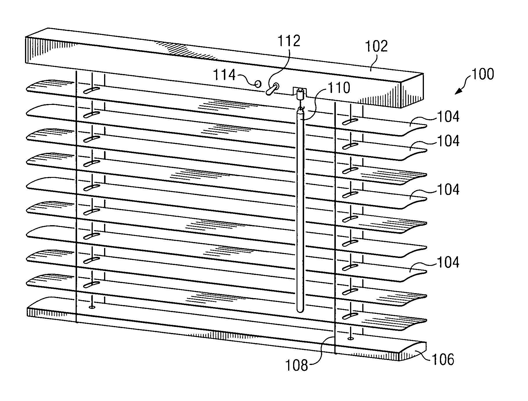
[0022] With reference to FIG. 1, the automated venetian blind is shown. As shown, the automated venetian blind 100 generally has the outward appearance of a standard venetian blind. The venetian blind may be a horizontal blind, a vertical blind, a mini blind or any other rotating slat blind assembly.
[0023] The automated venetian blind 100 includes a head rail 102. The head rail 102 contains mechanisms for raising, lowering and rotating the slats 104. The head rail 102 is attached by two or more lift cords 108 to a bottom rail 106. The lift cords 108 are typically in a ladder formation to facilitate rotation of the slats 104. A set of slats 104 are held suspended by the lift cords 108 to fill the space between the head rail 102 and the bottom rail 106. A baton 110 is attached to the head rail 102. Rotating the baton 110 rotates the slats between full open and full close positions.
[0024] An on-off switch 114 is mounted on the head rail 102. The on-off switch 114 is used to start and ...
second embodiment
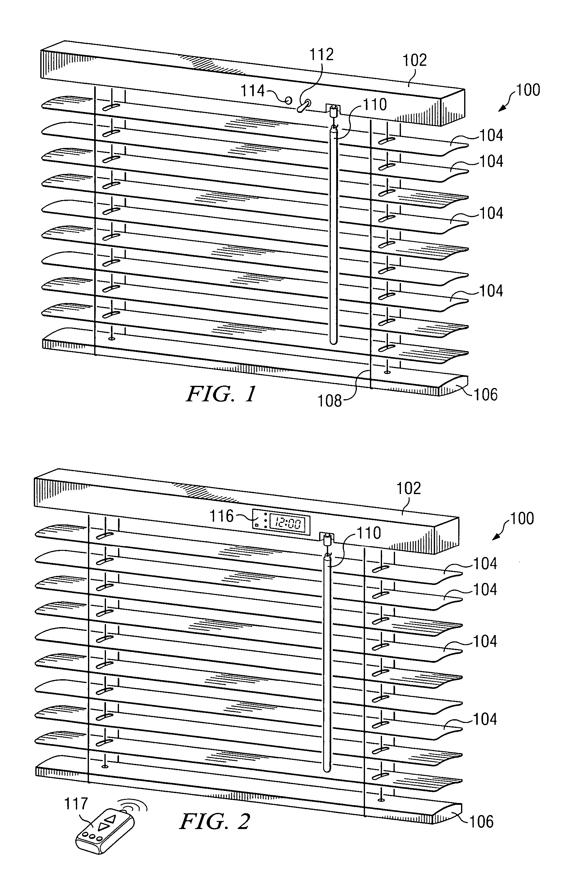
[0025] With reference to FIG. 2, the automated venetian blind 100 is shown. In this embodiment, a programmable interface 116 is mounted on the face of head rail 104. The programmable interface 116 may control the rotation of the slats in accordance with event programming, remote control instructions and / or light sensors. An infrared remote control 117 may be used to communicate with the programmable interface 116.
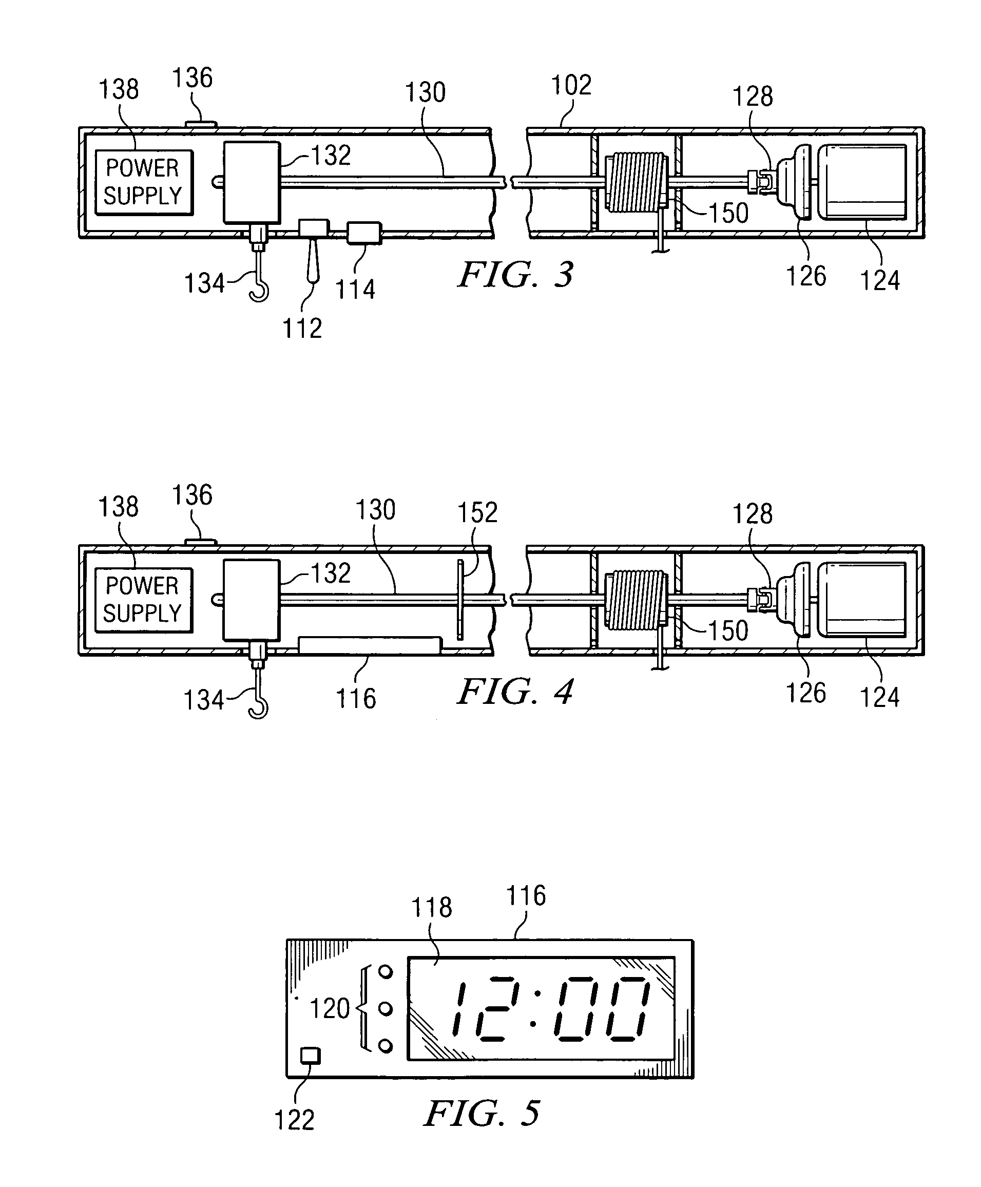
[0026] With reference to FIG. 3 and FIG. 4, the internal mechanisms of the head rail 102 are shown. The lift cords 108 of the venetian blinds are connected to spools 150. The spools 150 are attached to a shaft 130. By rotating the shaft 130, the spools 150 rotate causing the lift cords 108 to wind or unwind from the spools 150. This winding of the lift cords 108 around the spools 150 causes the slats 104 to rotate.
[0027] The shaft 130 is attached to a coupler 128. The coupler 128 is connected to the gear shaft of gear box 126, providing a mechanical connection of the shaft...
PUM
 Abstract
Description
Claims
Application Information
 - R&D
- Intellectual Property
- Life Sciences
- Materials
- Tech Scout
- Unparalleled Data Quality
- Higher Quality Content
- 60% Fewer Hallucinations
Browse by: Latest US Patents, China's latest patents, Technical Efficacy Thesaurus, Application Domain, Technology Topic, Popular Technical Reports.
© 2025 PatSnap. All rights reserved.Legal|Privacy policy|Modern Slavery Act Transparency Statement|Sitemap|About US| Contact US: help@patsnap.com


