Metal gasket

a metal gasket and metal technology, applied in the direction of engine seals, sealing arrangements, machines/engines, etc., can solve the problems of increasing the overall compression strength of the gasket, difficulty in constructing a seal that satisfies all, and affecting the sealing performance of the gasket, etc., to achieve soft compressibility, reduce the thickness, and control the effect of sealing beads

Inactive Publication Date: 2005-09-01
FEDERAL MOGUL WORLD WIDE +1
View PDF25 Cites 56 Cited by
  • Summary
  • Abstract
  • Description
  • Claims
  • Application Information

AI Technical Summary

Benefits of technology

[0011] One advantage of the present invention is that it provides a gasket of minimal thickness with relatively soft compressibility and controlled deformation of the sealing beads.
[0012] By extending fully across the sealing beads, the stopper layer has the beneficial effect of providing generally uniform compression of the complete

Problems solved by technology

Under these less than ideal sealing conditions, it is difficult to construct a seal that satisfies all of the criteria that such an application calls for.
The concern here is that the full collapse of the beads could cause at least some degree of overcompression and permanent deformation of the beads and thus impair the sealing performance of the gasket.
Consequently, the constrained functional layer compresses at a much

Method used


Image

  • Metal gasket
  • Metal gasket
  • Metal gasket

Examples


fourth embodiment

[0026]FIG. 6 illustrates a gasket 310 constructed according to the invention, wherein the same reference numerals are used to indicate like features, but are offset by 300. In this embodiment, the orientation of the first gasket layer 312 is reversed such that the sealing beads 326, 328 project inwardly toward one another, and that the stopper layer 316, joined to the second gasket layer 314 is preformed with a bead 52 that nests with the sealing bead 28 of the second layer 314.

fifth embodiment

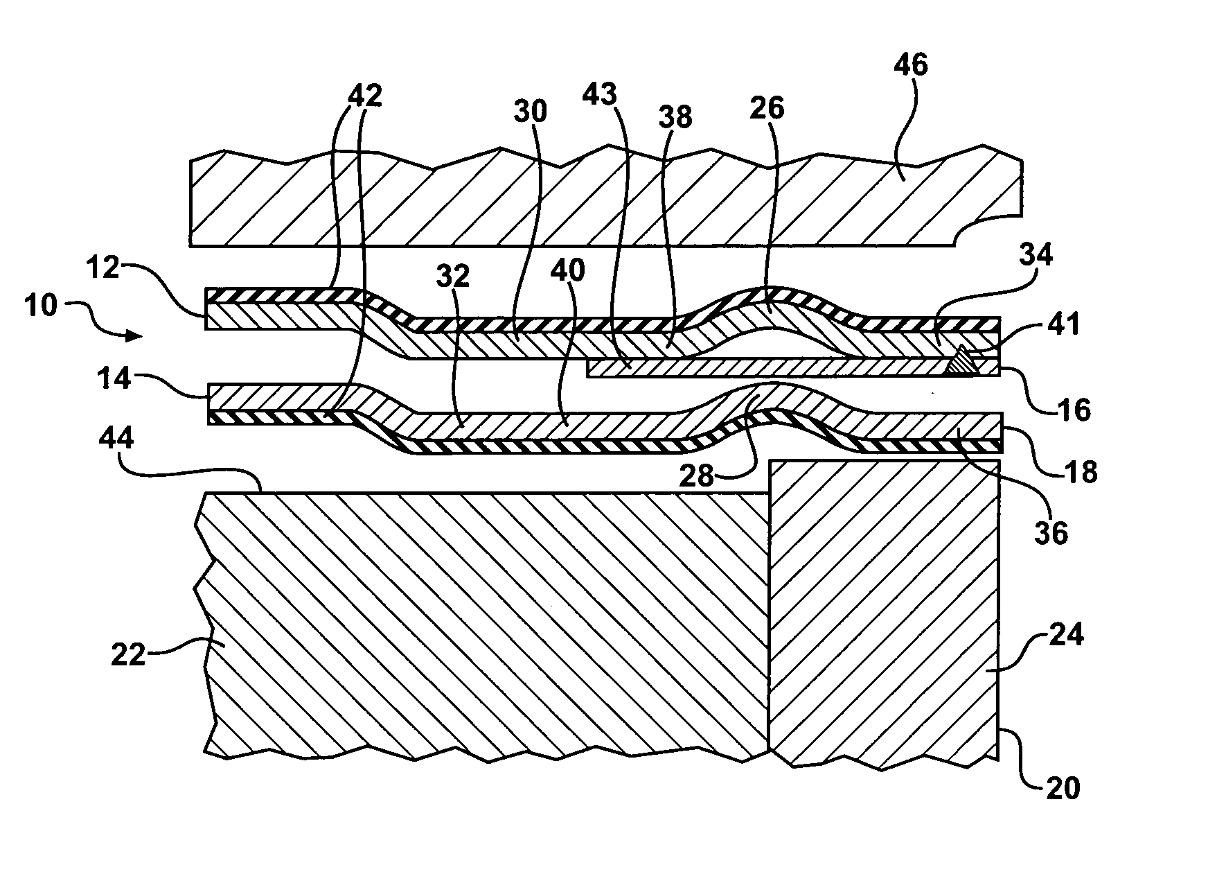
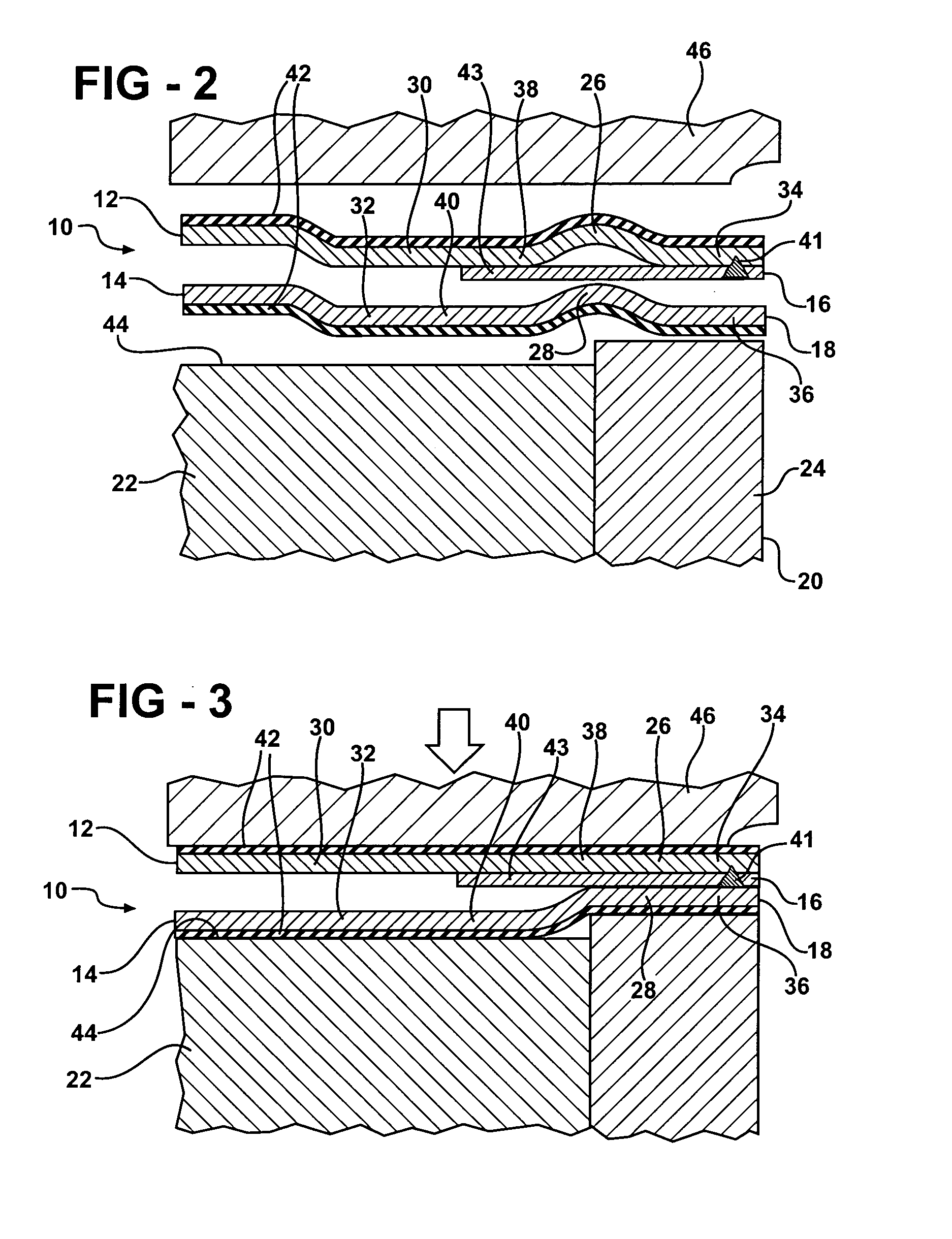
[0027]FIG. 7 illustrates a gasket 410 constructed according to the invention, wherein the same reference numerals are used to designate like features, but are offset by 400. In this embodiment, the gasket constriction is identical to that shown in FIG. 2, except that the attachment weld 441 is located on the raidally outboard side 443 of the stopper outward of the beads 426, 428 instead of on the radially inward side. The portion of the stopper layer 416 radially inward of the beads 426, 428 is free an unattached to either layer 412, 414. It will also be observed in FIG. 7 that the engine block 422 lacks a liner. This gasket 410 is equally applicable to engines with liners and engines without liners, as are each of the other embodiments of the invention described above. It is to be understood that within the scope of the present invention it is contemplated that the same outward location of the attachment weld 441 as shown in FIG. 7 could be applied to each of the other embodiments ...


PUM


Abstract

A multilayer metal gasket includes at least two metal gasket layers formed with an aligned opening and aligned opposing sealing beads surrounding the opening. A partial stopper layer is interposed between the gasket layers and is of lesser area than either of the gasket layers. The partial stopper layer extends from the opening outwardly beyond the sealing beads and is fixed to one of the layers on only one side of the sealing beads and is free on the opposite side.

Description

[0001] This application claims priority to U.S. Provisional Application Ser. No. 60 / 547,981, filed Feb. 26, 2004.BACKGROUND OF THE INVENTION [0002] 1. Technical Field [0003] This invention relates generally to multilayer metal gaskets, and particularly to those having at least two active bead layers separated by a partial stopper layer. [0004] 2. Related Art [0005] Multilayer metal gaskets are commonly used in engine applications to provide a seal between two members that are joined by bolting or other clamping means, such as between a cylinder head and an engine block, or between an exhaust manifold and the block. [0006] Various gasket configurations are known to the art and serve a variety of purposes. A particular application to which the present invention is directed is one in which the gasket is required to be of minimal thickness and able to seal effectively under fairly low contact pressure or able to conform to protrusions or recessions at the seal interface, such as in a cy...

Claims


Application Information

Patent Timeline
IPC IPC(8): F02F11/00F16J15/08
CPCF16J15/0825F16J2015/085F16J2015/0875F16J2015/0862F16J2015/0856
Inventor SCHMITZ, JEORG
Owner FEDERAL MOGUL WORLD WIDE
Why Eureka
Try Eureka