Regeneration control for hybrid vehicle

a hybrid vehicle and hybrid technology, applied in the direction of motor/generator/converter stopper, propulsion parts, engine-driven generators, etc., can solve the problems of frequent restriction of electric power storage devices, adversely affecting the driving performance of vehicles, and abrupt increase in engine rotation speed, so as to prevent the effect of rotation speed

Inactive Publication Date: 2005-09-01
NISSAN MOTOR CO LTD
View PDF6 Cites 100 Cited by
  • Summary
  • Abstract
  • Description
  • Claims
  • Application Information

AI Technical Summary

Benefits of technology

[0006] It is therefore an object of this invention to prevent the rotation speed of an engine of a hybrid vehicle from changing abruptly when regenerated energy exceeds an amount of power with which an electric power storage device can be charged during regeneration.

Problems solved by technology

In the prior art, however, when the electric power storage device (e.g. battery) has a small capacity, the charging power for the electric power storage device is frequently restricted because of its fully charged state and, as a result, the rotation speed of the engine often increases abruptly to consume surplus power.
An abrupt change in engine rotation speed makes the driver of the vehicle feel a sense of disagreement or makes it impossible to realize a desired braking force, and hence, may adversely affect the driving performance of the vehicle.

Method used


Image

  • Regeneration control for hybrid vehicle
  • Regeneration control for hybrid vehicle
  • Regeneration control for hybrid vehicle

Examples


Embodiment Construction

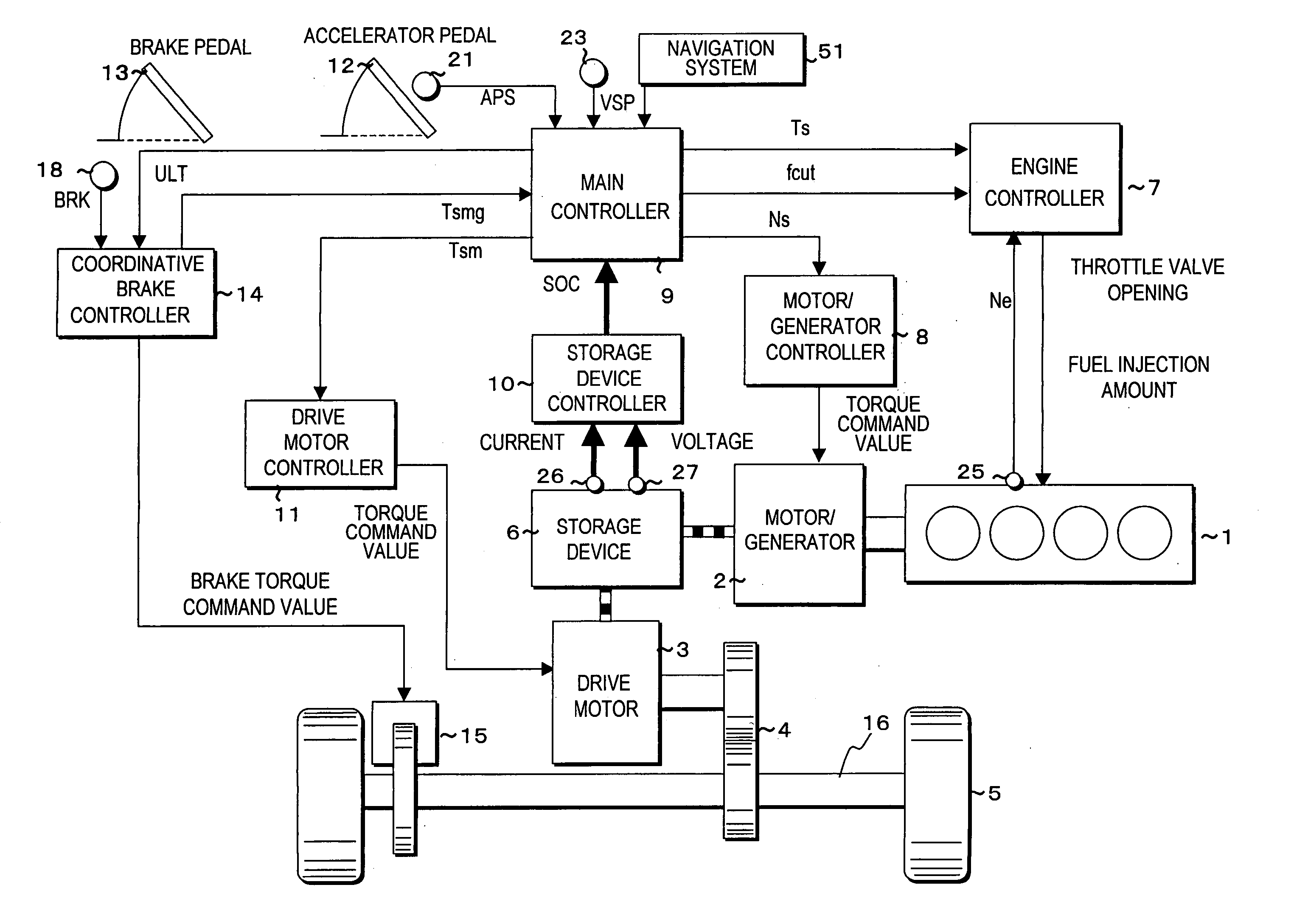
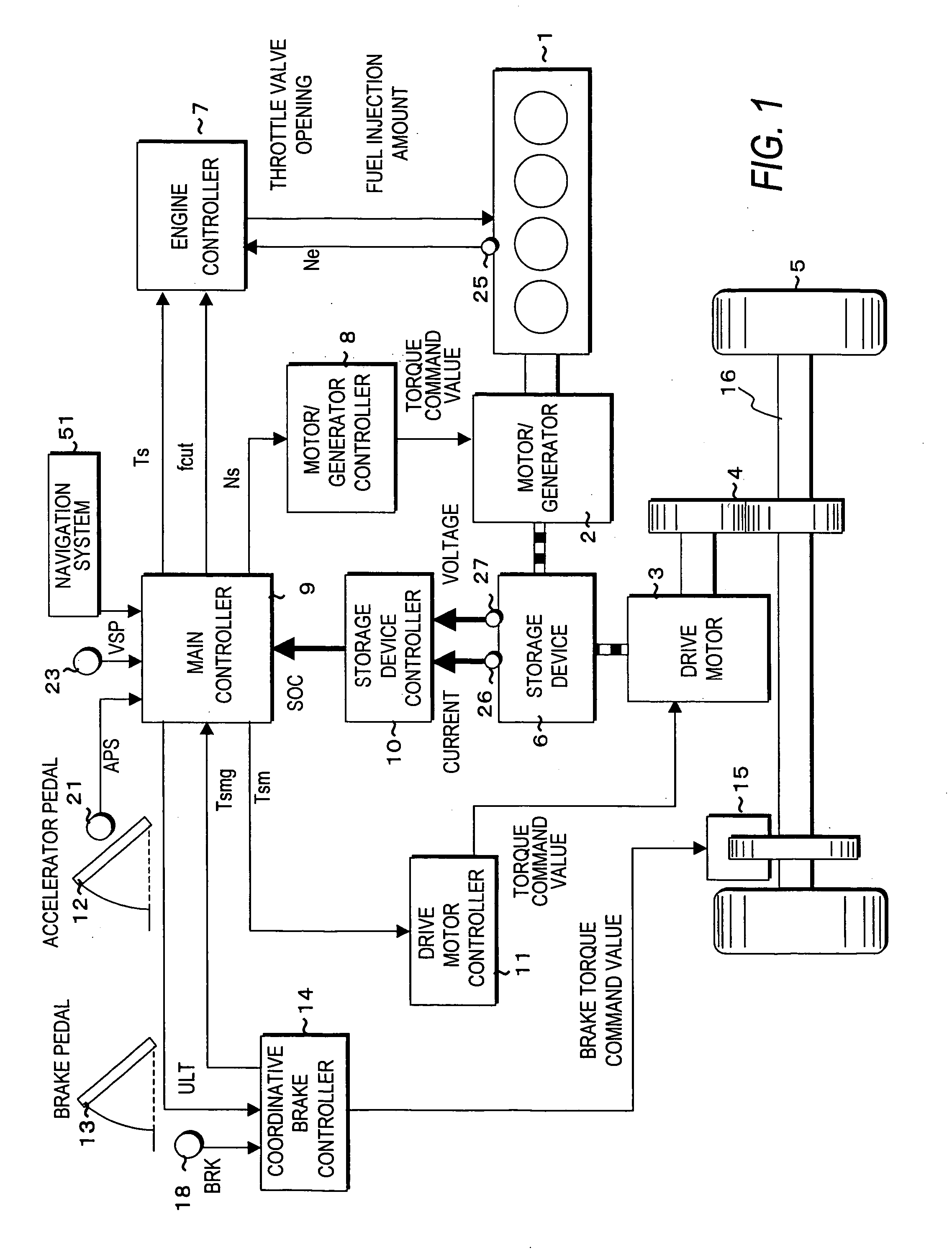
[0023]FIG. 1 shows a series hybrid vehicle to which this embodiment is applied.

[0024] The hybrid vehicle comprises an engine 1, a motor / generator 2, an electric power storage device 6, and a drive motor 3. The motor / generator 2 is directly coupled to the engine 1 and converts the output of the engine 1 into electric power. The electric power storage device 6 accumulates the power generated by the motor / generator 2. The drive motor 3 is driven by the power generated by the motor / generator 2 and / or the power accumulated in the electric power storage device 6. The motor / generator 2 mainly generates power but can also consume the power from the electric power storage device 6 or the regenerated power from the drive motor 3. Therefore, the motor / generator 2 functions as power generating means or power consuming means. The engine 1, the motor / generator 2, and the drive motor 3 constitute a power train. The torque of the drive motor 3 is transmitted to wheels 5 (tires) via a final gear 4 ...


PUM


Abstract

Disclosed is a control apparatus for a hybrid vehicle having an engine, a drive motor (3) that regenerates power, and an electric power storage device (6) that gives / receives power to / from the drive motor (3). The control apparatus includes power consumption means (2) for consuming power; a sensor (26, 27) that detects a state of charge of the electric power storage device; means (18, 23, 51) for detecting a driving state of the vehicle; and a controller (9). The controller (9) is programmed to calculate a chargeable energy amount Ecap in the electric power storage device (6) on the basis of a difference between a fully charged state of the electric power storage device and the detected state of charge; set a power |Pgen0| regenerated by the drive motor (3); calculate a chargeable power Pmax in the electric power storage device according to the detected state of charge; calculate a regenerated energy E resulting from regenerative braking from the detected driving state of the vehicle; calculate a charging power limit Pgenlmt according to the calculated regenerated energy E; and control the power consumption means (2) to consume a power equal to a difference between the power |Pgen0| regenerated by the drive motor (3) and the charging power limit |Pgenlmt| when the calculated regenerated energy E is greater than the chargeable energy amount Ecap in the electric power storage device and when the charging power limit |Pgenlmt| is smaller than the chargeable power |Pmax|.

Description

FIELD OF THE INVENTION [0001] This invention relates to regeneration control of a hybrid vehicle. BACKGROUND OF THE INVENTION [0002] A hybrid vehicle comprises an engine and a drive motor as its driving force sources. The drive motor generates power through rotation of driving wheels in braking the vehicle, and the generated power is accumulated as regenerated energy. This is known as an art called regenerative braking. [0003] In this regenerative braking, at the time of abrupt braking or the like, regenerated power may exceed the power with which a battery can be charged. [0004] In a hybrid vehicle disclosed in JP-2001-238303-A that was published by the Japan Patent Office in 2001, when regenerated power has exceeded the power with which a battery can be charged, surplus power is consumed by driving a motor / generator and an engine connected to the motor / generator. In addition, when there is a large amount of surplus power, the load applied to the engine is enhanced by actuating an ...

Claims


Application Information

Patent Timeline
Patent Type & Authority Applications(United States)
IPC IPC(8): B60K6/46B60W20/00B60L7/10B60L7/22B60L50/16B60W10/08B60W10/18B60W10/26H02P3/00
CPCB60K6/46Y02T90/162B60L7/26B60L11/123B60L15/025B60L2240/423B60L2240/622B60W10/08B60W10/26B60W20/00Y02T10/6217Y02T10/643Y02T10/7077Y02T10/7291Y02T90/16B60L7/22B60L50/61Y02T10/62Y02T10/64Y02T10/72Y02T10/70B60W10/06Y02T10/7072
Inventor KOMIYAMA, SUSUMUIWANO, HIROSHIYAMAGUCHI, MUSASHIWATANABE, HIDEAKI
Owner NISSAN MOTOR CO LTD
Why Eureka
Try Eureka