Dot-gain reduction method for multi-level halftoning

a technology of dot gain and reduction method, applied in the field can solve problems such as problems such as dot gain, and achieve the effect of reducing dot gain

Inactive Publication Date: 2005-09-01
SHARP KK
View PDF2 Cites 7 Cited by
  • Summary
  • Abstract
  • Description
  • Claims
  • Application Information

AI Technical Summary

Problems solved by technology

It is typical for dot gain to become a problem in, for example, an imaging, or printing, system wherein an output color image is delivered as a halftoned image.

Method used


Image

  • Dot-gain reduction method for multi-level halftoning
  • Dot-gain reduction method for multi-level halftoning
  • Dot-gain reduction method for multi-level halftoning

Examples


Embodiment Construction

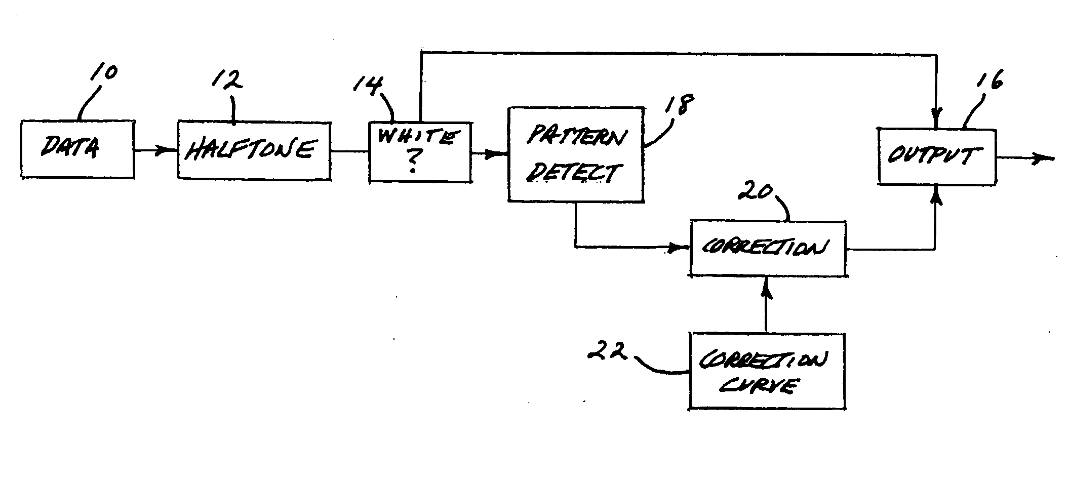
[0012] Turning now to the drawings, and referring first of all to FIG. 1, this diagram generally illustrates a preferred manner of practicing of the invention to minimize dot gain in an output, halftoned color image which is furnished as output by a color-imaging, multi-level, halftone image output device. Seven operatively interconnected blocks 10, 12, 14, 16, 18, 20, 22 are shown in FIG. 1.

[0013] Block 10 represents initially non-halftoned color-image input pixel data which, downstream from block 10, is appropriately and conventionally halftoned in block 12. From block 12, flowing halftoned pixel data is examined in block 14 to distinguish white pixels from colored pixels, with white pixels from there sent directly for ultimate outputting by output device 16 which herein, for illustration purposes, takes the form of a CMYK printer, and with colored pixels being sent to block 18 for further scrutiny.

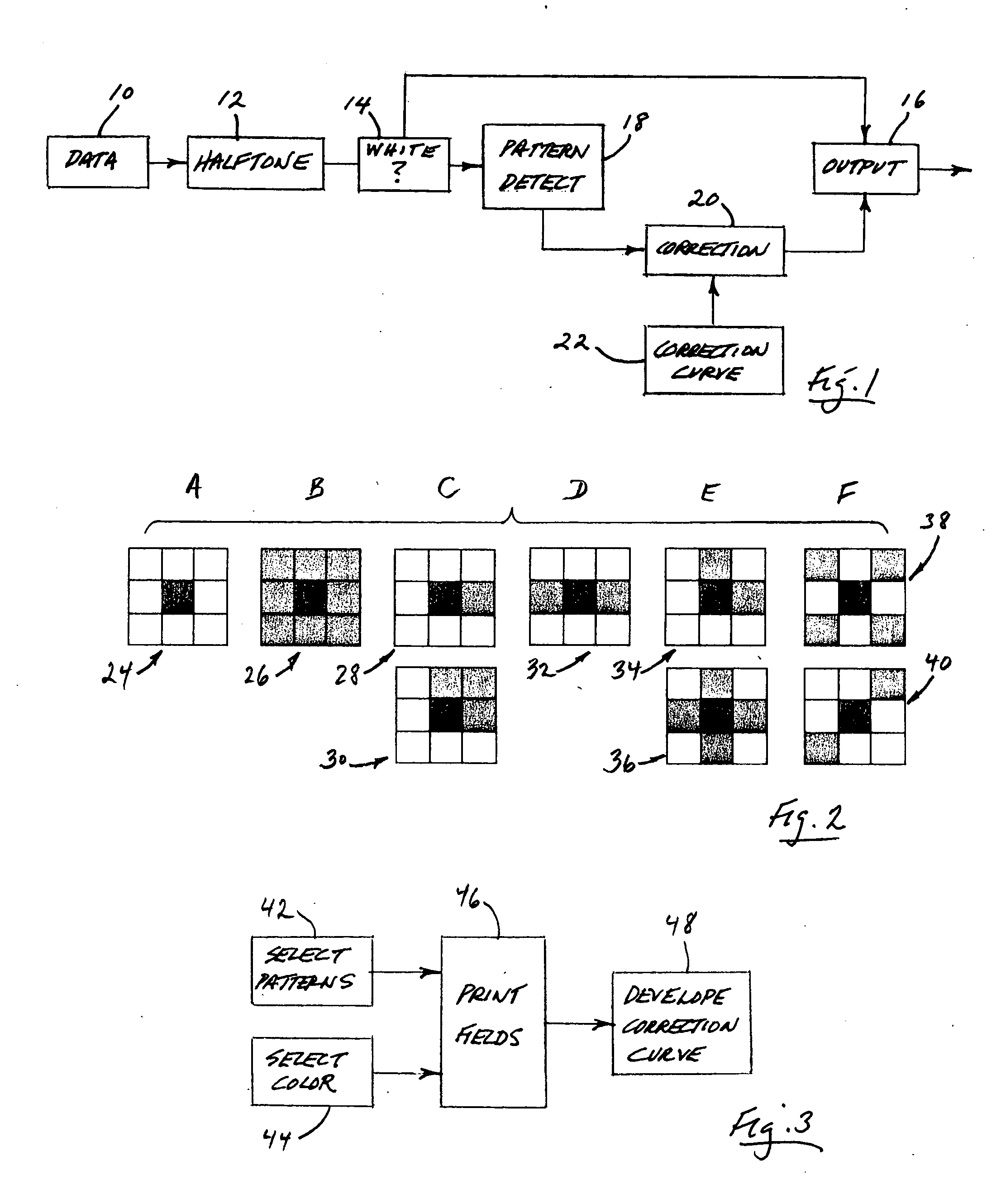
[0014] Halftoned pixel data directed to block 18 is examined to detect, with rega...


PUM


Abstract

A method for minimizing color-image halftone dot-gain in the output of a multi-level halftone color-imaging output device. The method includes characterizing that device's halftone output, on a per-color basis, regarding pixel-pattern-specific dot gain which can be related to device pixel-infeed intensity levels, and from that characterizing, creating, and then applying to throughput color-image files, on a pixel-by-pixel basis, and for each output color producible by the device, a pixel-to-device infeed intensity correction value, thus to minimize device-output dot gain.

Description

BACKGROUND AND SUMMARY OF THE INVENTION [0001] This invention relates to a method for reducing dot gain with respect to the operation of a multi-level halftoning color-image output device. More specifically, it relates to such a method which is based upon the output-device-specific creation of a pixel infeed intensity correction curve which is employed for adjusting pixel infeed intensity with regard to the feeding of a pixel into a selected multi-level halftone image output device. More particularly, the term “pixel infeed” as used herein specifically refers to the feeding in to such an output device of a colored pixel for ultimate outputting by that device. For the purposes of illustration herein, a preferred manner of practicing the present invention is described in a context where the image output device is a CMYK, multi-level, halftone printer. [0002] It is typical for dot gain to become a problem in, for example, an imaging, or printing, system wherein an output color image is...

Claims


Application Information

Patent Timeline
Patent Type & Authority Applications(United States)
IPC IPC(8): H04N1/40H04N1/407H04N1/52H04N1/58
CPCH04N1/407H04N1/40087
Inventor CHANG, CHING-WEI
Owner SHARP KK
Why Eureka
Try Eureka