
Method of triggering application service using filter criteria and IP multimedia subsystem using the same

a technology of application service and filter criteria, applied in the field of ip multimedia subsystem, can solve the problems of increased run time delay and traffic in the servers, and increased application server load, so as to reduce the number of unnecessary sip message relays and improve the efficiency of establishing session calls

Inactive Publication Date: 2005-09-01
IND TECH RES INST
View PDF5 Cites 153 Cited by
  • Summary
  • Abstract
  • Description
  • Claims
  • Application Information

AI Technical Summary

Benefits of technology

The present invention provides a method for controlling IP multimedia services using a state filter criteria (stFC). The stFC defines specific user states and session states for triggering each application service provided by the service provider. The S-CSCF monitors the session or service initiated by a SIP request message and triggers an application server if the stFC matches the session state or user state. The S-CSCF records the SIP request message for the use of triggering AS or performing extra services. The invention improves the efficiency of establishing session calls, simplifies the operational configuration of application servers, and provides a flexible multimedia service control capability to the S-CSCF. The stFC is compatible with the 3GPP standard and requires storage of stFC-related information in the user profile and the S-CSCF requires the ability to process the stFC information. The invention also provides an IP multimedia subsystem comprising at least one S-CSCF, at least one application server, and a HSS.

Problems solved by technology

In certain situations, the decision to trigger the application servers cannot be determined by the SIP request message, forwarding of which to the application servers thereby wastes the resources and increases application server loading.
The triggering procedure thus becomes very complicated and results in increased run time delay and traffic in the servers.

Method used


Image

  • Method of triggering application service using filter criteria and IP multimedia subsystem using the same
  • Method of triggering application service using filter criteria and IP multimedia subsystem using the same
  • Method of triggering application service using filter criteria and IP multimedia subsystem using the same

Examples


Embodiment Construction

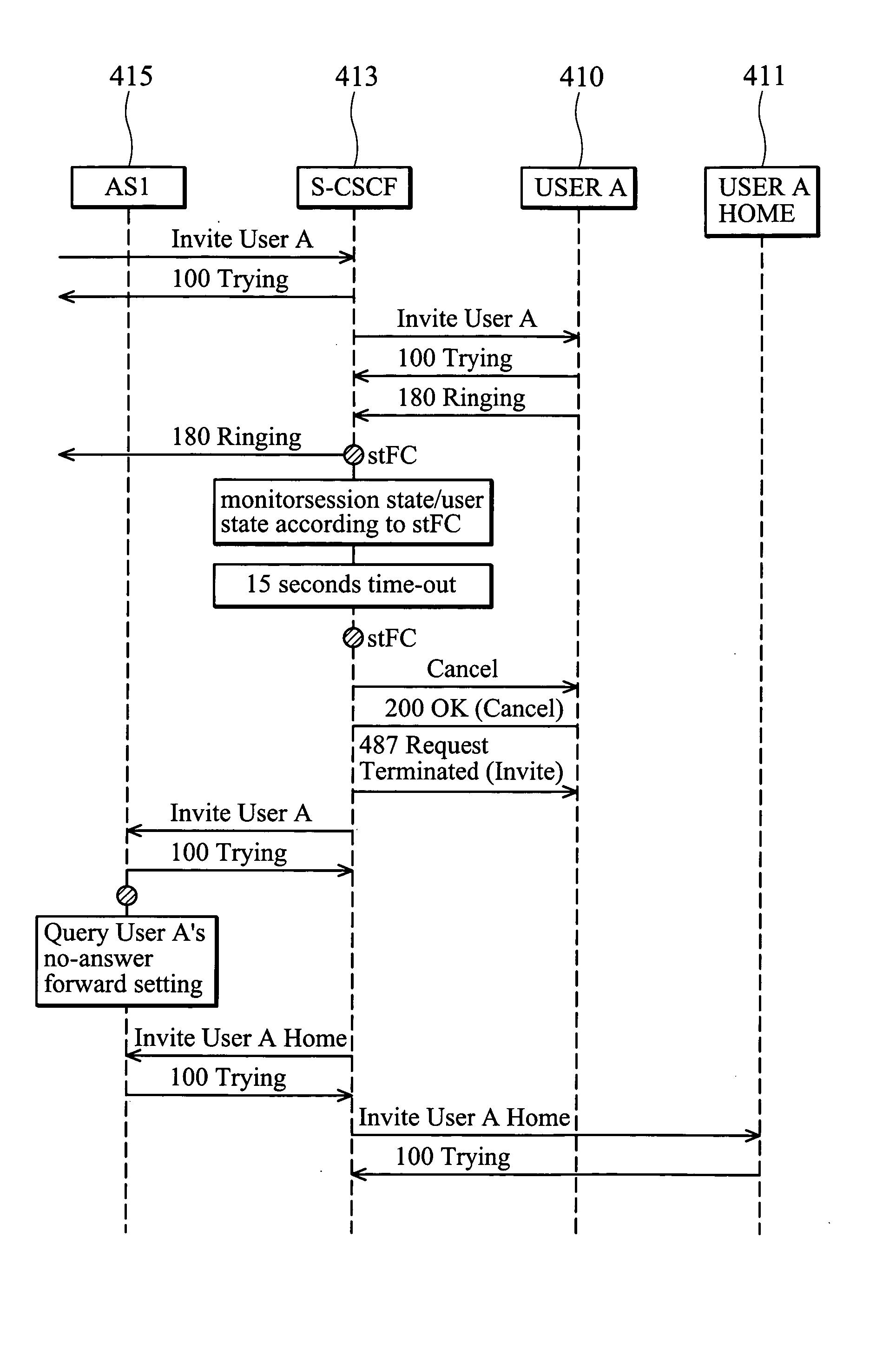
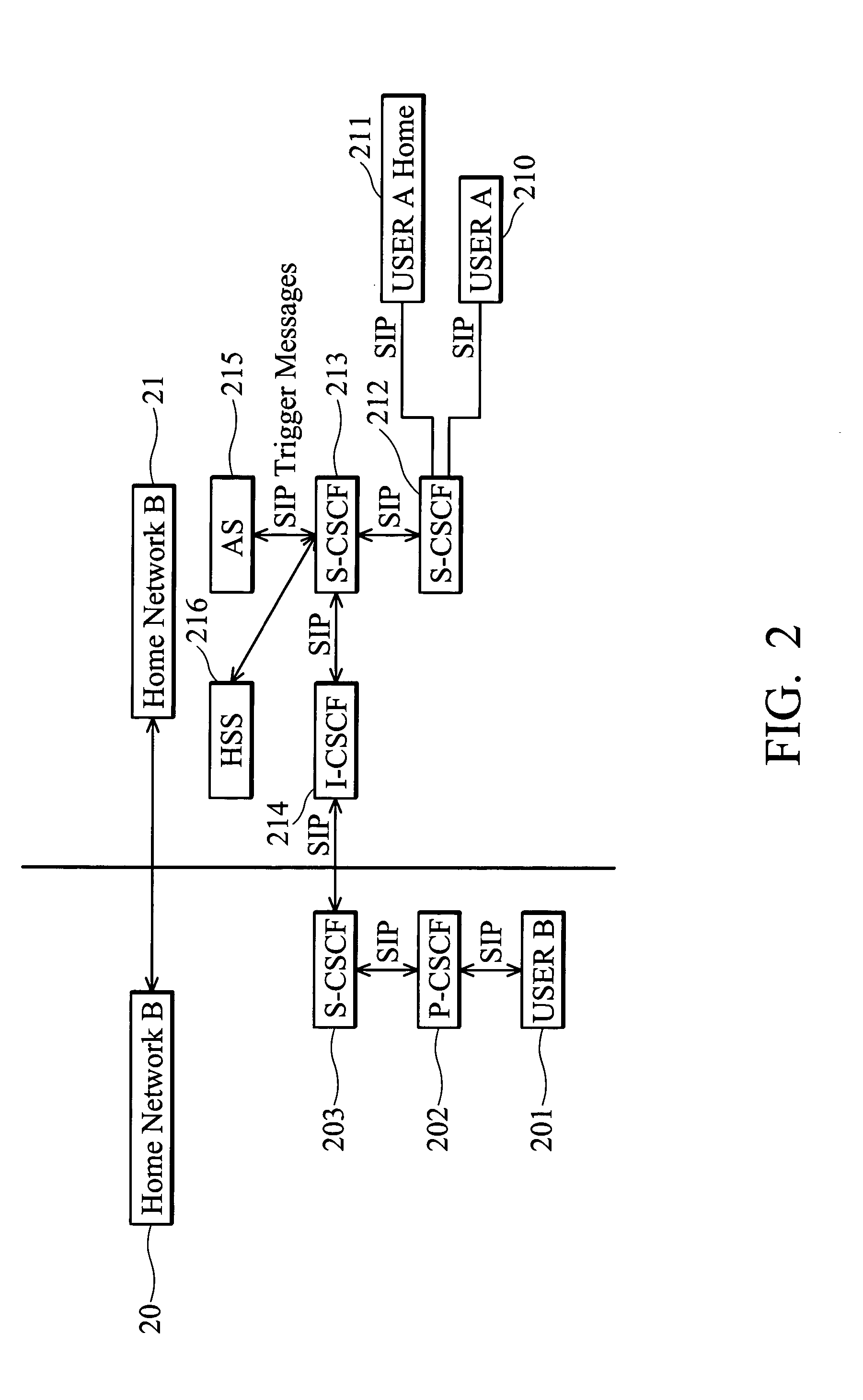
[0026]FIGS. 4a and 4b illustrate the SIP message flow sequence in the case of call forwarding to User A home when User A is busy, the same example shown in FIG. 2. FIG. 4a shows the SIP message flow in the IP multimedia subsystem only using the iFC scheme, whereas FIG. 4b shows the SIP message flow in the IP multimedia subsystem using the stFC scheme disclosed in the present invention.

[0027] As shown in FIG. 4a, a user B originates an SIP invitation message according to the standard 3GPP IMS to request call initiation with user A 210. The SIP invitation message passes to the S-CSCF 213 of user A's home network, and the S-CSCF 213 passes it to an application server (AS1) 215. AS1215 is designated for call forwarding in response to no-answer, and is responsible for monitoring the state of user A 210. After 15 seconds of ringing, AS1215 terminates the request to user A 210 and invites user A home 211. As shown in the diagram, all messages pass through AS1215 and S-CSCF 213, which comp...


PUM


Abstract

A triggering method for IP multimedia service control. The triggering method comprises monitoring a session state or user state according to a set of specific filter criteria, recording a corresponding SIP request message, and triggering an application server designated by the criteria if a trigger point thereof matches the session state or user state. Furthermore, the SIP-server performs additional action effectively manage the session or services according to the Action defined in the user profile. The scheme is suited to application services triggered according to session state or user state, and is compatible with the iFC scheme defined in 3GPP. The present invention improves the efficiency of communication and enhances the flexibility of the SIP server.

Description

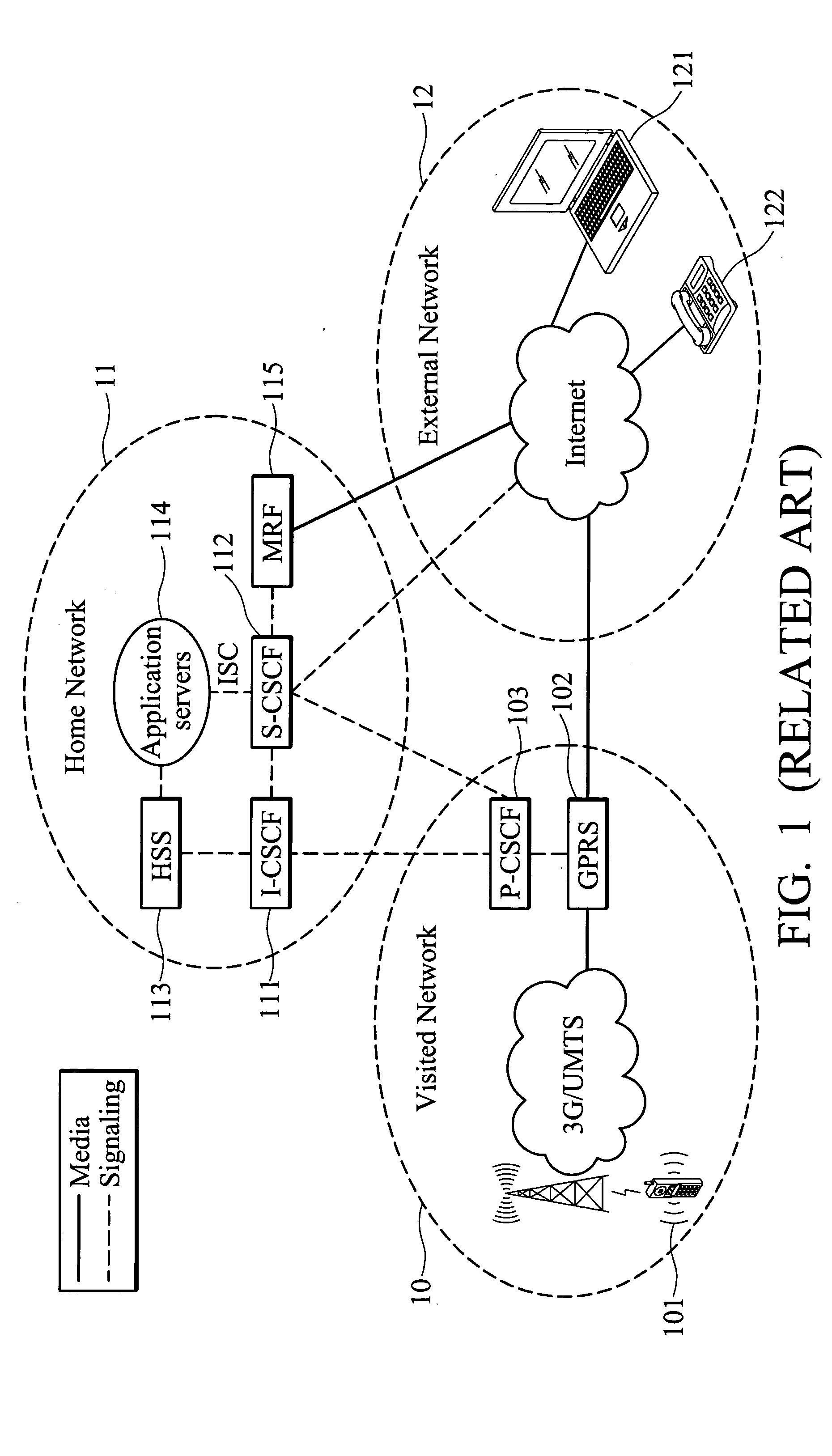
BACKGROUND OF THE INVENTION [0001] 1. Field of the Invention [0002] The present invention relates to an IP multimedia subsystem, and more specifically, to an application triggering method of a 3GPP IP multimedia subsystem using specific filter criteria. [0003] 2. Description of the Related Art [0004]FIG. 1 illustrates an example of the architecture of a 3GPP (Third Generation Partnership Project) IP (Internet Protocol) multimedia subsystem. The IP multimedia subsystem is divided into visited network 10, home network 11, and external network 12. As shown in the diagram, User Equipment (UE) 101 in the visited network connects to the General Packet Radio Service (GPRS) system 102 through a 3G / UMTS communication network. There is a Proxy Call Session Control Function (P-CSCF) 103 in the visited network for communication with an Interrogating CSCF 111 (I-CSCF) and a Serving CSCF (S-CSCF) 112 in the home network 11. The Home Subscriber Server (HSS) 113 stores subscriber-related informatio...

Claims


Application Information

Patent Timeline
Patent Type & Authority Applications(United States)
IPC IPC(8): H04L12/24H04L12/28H04L12/56H04L29/00H04L29/06H04L29/08
CPCH04W4/00H04W24/00H04W80/00H04L67/14H04L65/1006H04L67/16H04L67/306H04L65/1016H04L65/1104H04L67/51
Inventor TSAI, SHANG-CHIHCHIANG, WEI-KUOCHEN, CHUN-MIN
Owner IND TECH RES INST
Learn More