Fixing apparatus and an image formation apparatus

a technology of fixing apparatus and fixing member, which is applied in the direction of electrographic process apparatus, ohmic-resistance heating, instruments, etc., can solve the problems of uneven heat distribution of the fixing member in the width direction, difficult control of the temperature on both ends of the fixing member, and rapid rise of the temperature of the fixing apparatus

Active Publication Date: 2005-09-01
RICOH KK
View PDF3 Cites 51 Cited by
  • Summary
  • Abstract
  • Description
  • Claims
  • Application Information

AI Technical Summary

Benefits of technology

[0074] According to the present invention, the heating range in the width directions of the fixing member is made variable by using the shielding member that shields a part of the core unit, and the end positions in the width directions of the core unit are projected toward the coil unit, and
[0075] the heating range in the width directions of the fixing member can be finely adjusted by using the shielding member that shields a part of the core unit.
[0076] In this manner, the temperature rise at both ends of the fixing member in the width directions is suppressed, even when a small width recording medium is continuously fixed; and the fixing apparatus and the image formation apparatus that are capable of providing satisfactory fixing to different widths of the recording media are offered.

Problems solved by technology

Image formation apparatuses having the conventional fixing member as described above have various problems caused by preventing the temperature rise at both ends in the width directions when fixing a recording medium having a small width.
When the fixing apparatus processes the recording media having different widths, heat distribution of the fixing member in the width directions becomes uneven depending on the widths of the recording media.
While controlling the temperature of the central position of the fixing member in the width directions is possible, it is difficult to control the temperature on both ends of the fixing member, where the temperature undesirably rises.
Especially, with the fixing member using the IH method, the temperature of the fixing apparatus quickly rises.
Further, if the temperature of both ends exceeds a thermal breakage temperature, it is conceivable that the fixing member will be thermally damaged, and the service life of the fixing member will be shortened.
Due to the complicated structure and control, the solution tends to be costly.
Further, since there arise gaps between the electromagnetic induction coils, the temperature of the heating member at positions corresponding to the gaps tends to be lower than required, causing poor fixing at the positions.
Accordingly, the structure and control tend to be complicated, and cost tends to be high.
Further, there arise gaps between the core units.
Positions on the heating member corresponding to the gaps cannot be properly heated, causing poor fixing at the positions.
For this reason, when a recording medium with a great width is to be fixed, poor fixing tends to occur at both ends of the recording medium in the width directions.

Method used


Image

  • Fixing apparatus and an image formation apparatus
  • Fixing apparatus and an image formation apparatus
  • Fixing apparatus and an image formation apparatus

Examples


embodiment 1

[0090] Embodiment 1 of the present invention is described in detail with reference to FIGS. 1 through 4.

[0091] First, the overall structure and operation of an image formation apparatus 1 according to Embodiment 1 are described.

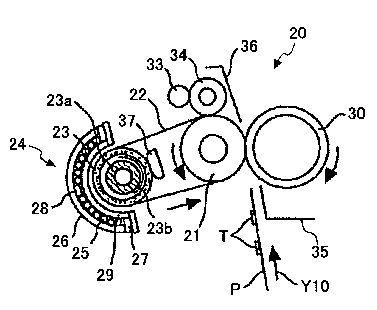
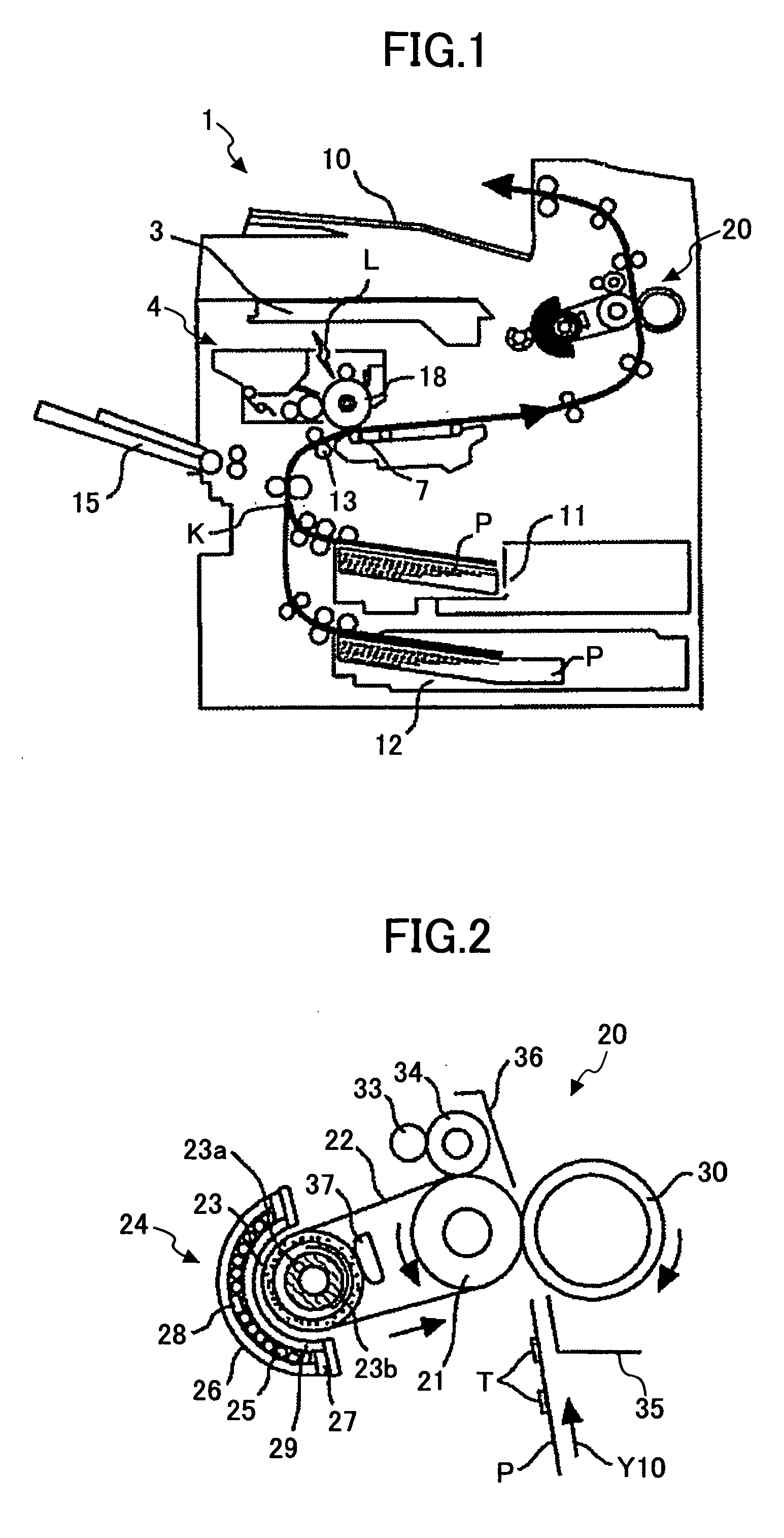
[0092] As shown in FIG. 1, the image formation apparatus 1 includes an exposure unit 3 that irradiates an exposure light L based on image information to a photo conductor drum 18, a process cartridge 4 that is detachably installed in the image formation apparatus 1, a transferring unit 7 that transfers a toner image formed on the photo conductor drum 18 to a recording medium P, a delivery tray 10 to which an output image is discharged, feed units 11 and 12 that store the recording media P, such as imprint paper, a resist roller 13 that conveys the recording medium P to the transferring unit 7, a manual feed unit 15 that feeds a recording medium P often having sizes different from the recording medium P stored by the feed units 11 and 12, and a fixing unit 2...

embodiment 2

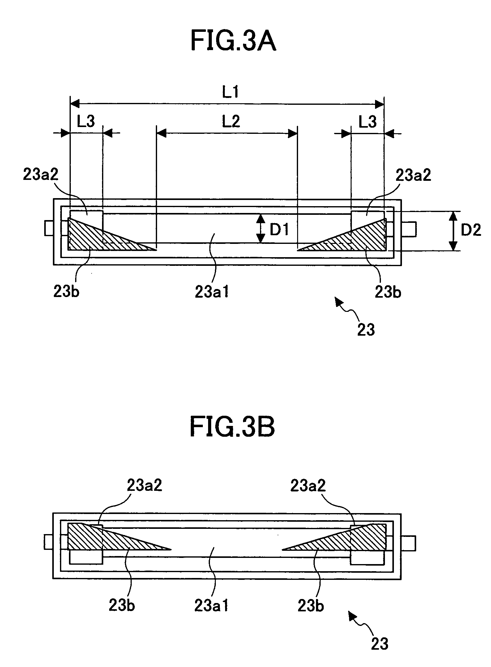
[0132] Embodiment 2 of the present invention is described in detail with reference to FIG. 5, which is a cross-sectional drawing showing the heating roller 23 installed in the fixing apparatus 20 according to Embodiment 2, and corresponds to FIG. 3A of Embodiment 1. As shown in FIG. 5, the shape of the internal core 23a (constituted by the small diameter section 23a1 and the large diameter sections 23a2), and the shape of the shielding members 23b are different from Embodiment 1.

[0133] The internal core 23a that is shaped like a solid cylinder having the large diameter sections 23a2, and the shielding members 23b are rotatably installed in the hollow cylinder of the heating roller 23 as shown in FIG. 5.

[0134] The large diameter sections 23a2 of the internal core 23a differ from those of Embodiment 1 in that the center axis of the large-diameter sections 23a2 is eccentric to (different from) the center axis of the small diameter section 23a1. The direction of the eccentricity is a ...

embodiment 3

[0139] Embodiment 3 of the present invention is described in detail with reference to FIG. 6 that is a cross-sectional drawing showing the heating roller 23 installed in the fixing apparatus 20 according to Embodiment 3, and corresponds to FIG. 3A of Embodiment 1. The shape of the internal core 23a installed in the heating roller 23 of Embodiment 3 differs from Embodiment 1.

[0140] The hollow cylinder of the heating roller 23 includes the internal core 23a that is shaped like a solid cylinder having the large diameter sections 23a2, and the shielding members 23b that are rotatably installed as shown in FIG. 6.

[0141] The internal core 23a differs from Embodiment 1 in that taper sections 23a3, each having a width L4, are provided between each large diameter section 23a2 and the small diameter section 23a1.

[0142] The shielding members 23b are formed so that the shielded range wherein the internal core 23a is shielded can be increased from the edge of the internal core 23a, and decrea...


PUM


Abstract

A fixing apparatus and an image formation apparatus therewith are disclosed. According to the fixing apparatus, a heating range that is heated by electromagnetic induction caused by a current flowing through a coil unit is finely tunable by covering a part of a core unit with a shielding member. Further, the core unit has a projecting section at an end of the core unit, which projecting section projects toward the coil unit in comparison with the central part of the core unit.

Description

BACKGROUND OF THE INVENTION [0001] 1. Field of the Invention [0002] The present invention generally relates to an image formation apparatus using electro photography, such as copying machines, printers, facsimile apparatuses, and compound machines; and a fixing apparatus thereof. Further, the present invention especially relates to a fixing apparatus and an image formation apparatus that are capable of forming an image on two or more kinds of recording media that have different dimensions. [0003] 2. Description of the Related Art [0004] A fixing apparatus using an electromagnetic-induction heating (IH) method has been known, which aims at saving energy by shortening the standup time of an image formation apparatus, such as a copying machine and a printer (for example, Patent Reference 1). [0005] According to Patent Reference 1, for example, the fixing apparatus of an electromagnetic-induction heating method includes a fixing belt, serving as a fixing member, that is installed with t...

Claims


Application Information

Patent Timeline
Patent Type & Authority Applications(United States)
IPC IPC(8): G03G21/00G03G15/20
CPCG03G2215/20G03G15/2053G03G15/2042
Inventor UENO, SATOSHIOMURA, KEN
Owner RICOH KK
Why Eureka
Try Eureka