

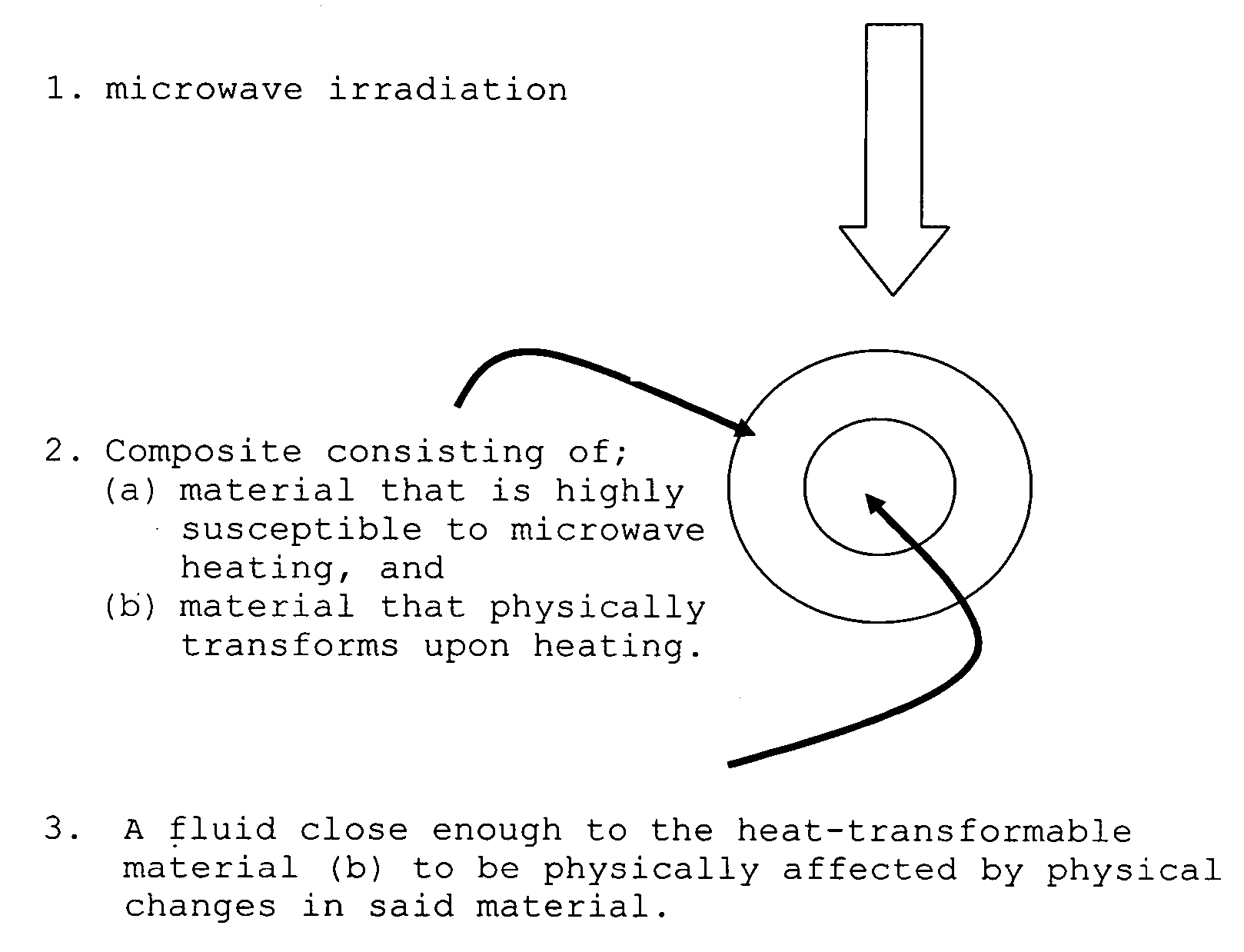
Microwave microfluidics
a microfluidic and microwave technology, applied in the field of microwave heating, can solve the problems of fluid movement, poor heating of other materials, and less efficient heating of surfaces, even if non-contact, and achieve the effect of fast heating of surfaces
- Summary
- Abstract
- Description
- Claims
- Application Information
AI Technical Summary
Problems solved by technology
Method used
Image

Examples
example 1
Heat-Shrink Tubing Coated with Dielectric
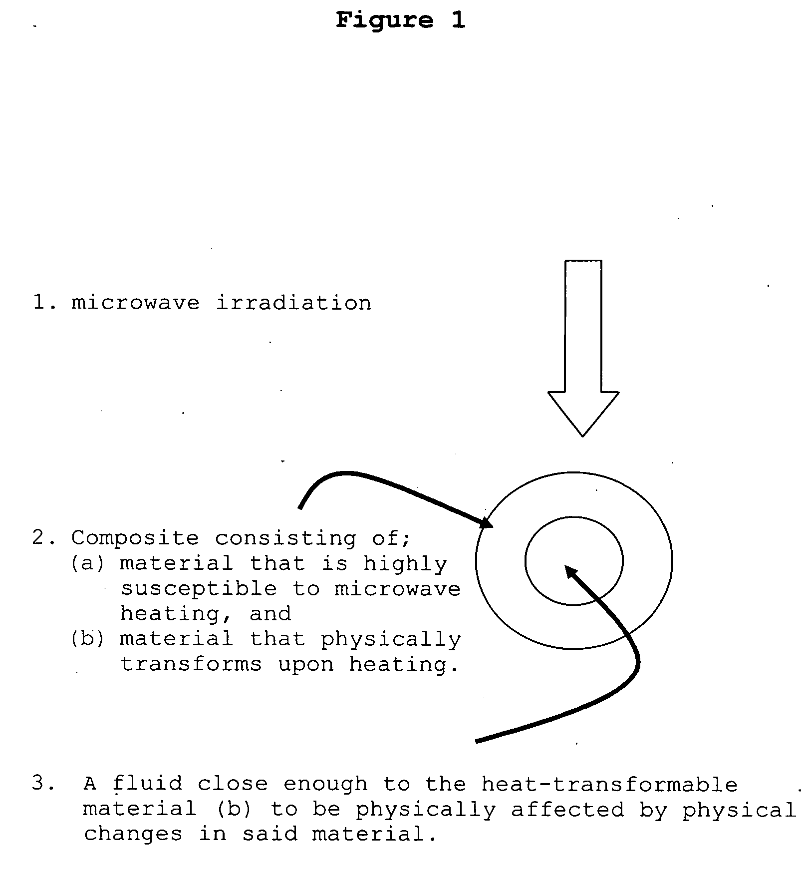
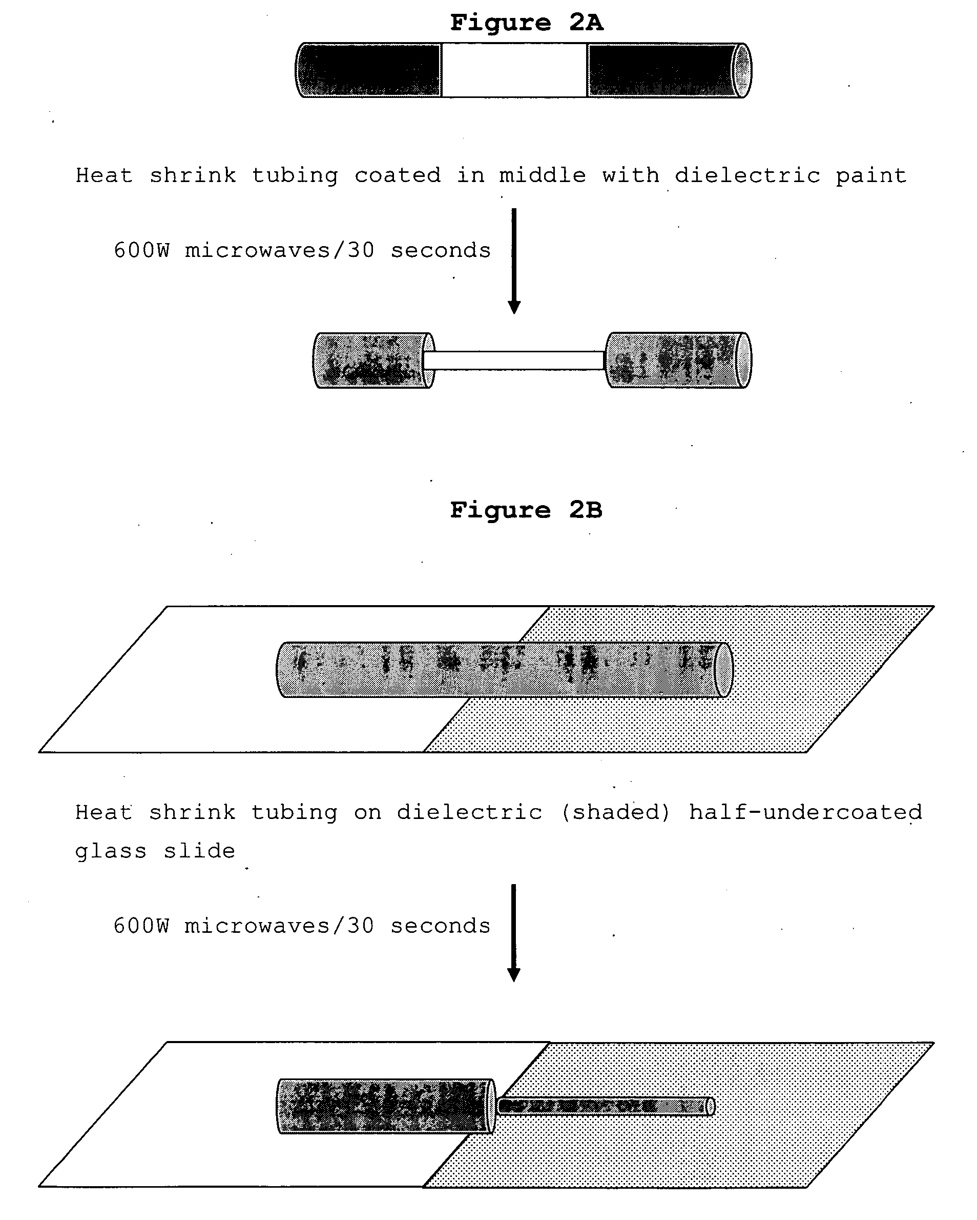
[0120] Short lengths (approximately 3-5 cm) of polyolefin-based heat shrink tubing (22-18 AWG, Gardner Bender, Milwaukee, Wis.) were partially painted with dielectric paint. The paint was a mixture of BaTiO3 powder and polyvinyl acetate aqueous adhesive (Elmer's Glue-All®) blended to a consistency of common toothpaste. The middle third segment of tubing was painted entirely around and the two outside thirds were left bare. After the paint had dried, the tubing was placed in a microwave oven (600 W) and microwaved for 30 seconds. The diameter painted middle segment of the tubing constricted by about 50%, while the outside segments remained the same diameter (FIG. 2A).
[0121] In another experiment, tubing was wrapped with a piece of carbon-based adhesive-backed dielectric (BSR-1 / SS6M, Emerson & Cuming). This dielectric was purchased in silicone-based thin (0.01″) sheets, which were cut with a razor blade to the appropriate dimensions. As above...
example 2
Microwave Microfluidics using Heat Shrink Tubing-Dielectric Composite
[0124] Example 1 showed that a composite of microwave-active material and heat shrink polymer responded rapidly and markedly to mild microwave irradiation. Microwaving the composite caused constriction of the heat shrink tubing. The composites can be considered “smart materials”. We next tested the composites to determine if they could be used to move liquids, as a result of the force of contraction observed upon microwaving.
[0125] A microfluidic chip (FIG. 3) was assembled starting with a nitrocellulose membrane-coated microscope slide. Underneath the slide, two pieces of microwave-active adhesive dielectric material were affixed to the glass—MCS / SS6M (0.04″ thick) and BSR-1 / SS6M (0.01″ thick)(Emerson & Cuming). On top of the slide (the nitrocellulose side) was glued a length of heat shrink tubing (311640, Squire Electronics). The tubing had been filled with an oxidant solution (62.5 mM NaBO3, 100 mM NaHCO3, 0.0...
example 3
Preparation of Dielectric / Wax Composites
[0128] Examples 1 and 2 describe tube or channel microfluidics. Another embodiment is vesicle microwave microfluidics. Here, vesicles enclose a fluid of choice. The vesicles are designed to melt upon mild microwave irradiation. This is accomplished by using a composite containing a microwave-active material and a material with a melting point that is between typical room temperature (20° C.) and the boiling point of water (100° C.).
[0129] A standard glass microscope slide (1″×3″) was undercoated with a piece of dielectric (adhesive-backed BSR-1, Emerson & Cuming, Randolph, Mass.)(FIG. 4). Wax was chosen as an encapsulating material because of its low melting point (approx. 55° C.) and its resistance to direct microwave heating. Shavings of paraffin wax were placed on the slide and the slide was microwaved until the wax melted. Excess wax was decanted from the slide leaving a thin film of wax, which rapidly hardened. The dielectric was remove...
PUM
| Property | Measurement | Unit |
|---|---|---|
| wavelength | aaaaa | aaaaa |
| temperature | aaaaa | aaaaa |
| temperature | aaaaa | aaaaa |
Abstract
Description
Claims
Application Information