Mobile terminal-based remote control technique

a mobile terminal and remote control technology, applied in the field of mobile terminal-based remote control techniques, can solve the problems of insufficient display of information, inability to smooth the operation of the remote control, and inability to adjust the display of information, so as to achieve the effect of ensuring the accuracy of the remote control of the specified devi

Inactive Publication Date: 2005-09-01
SEIKO EPSON CORP
View PDF9 Cites 19 Cited by
  • Summary
  • Abstract
  • Description
  • Claims
  • Application Information

AI Technical Summary

Benefits of technology

[0029] The remote control method of the invention causes the mobile terminal to function as the operation signal transmitter that converts a signal input by the operation unit into an operation signal for the specified device, sends the operation signal, and outputs and displays support information regarding the operation of the specified device on the display unit. The mobile terminal is thus used as the operation signal transmitter for remote controlling the specified device, while the support information is displayed on the display unit of the mobile terminal. The user refers to the support information displayed on the display unit of the mobile terminal and thereby readily remote controls the specified device. A typical example of the ‘mobile terminal’ is a cell phone.

Problems solved by technology

Inexperienced users may have difficulties in smooth operations of the remote control and may thus be forced to refer to the written instructions manual for the smooth operations of the remote control.
The displayed information may, however, be insufficient because of the limited space of the TV screen.
Such constant display of information may, on the other hand, be rather annoying to experienced users.

Method used


Image

  • Mobile terminal-based remote control technique
  • Mobile terminal-based remote control technique
  • Mobile terminal-based remote control technique

Examples


Embodiment Construction

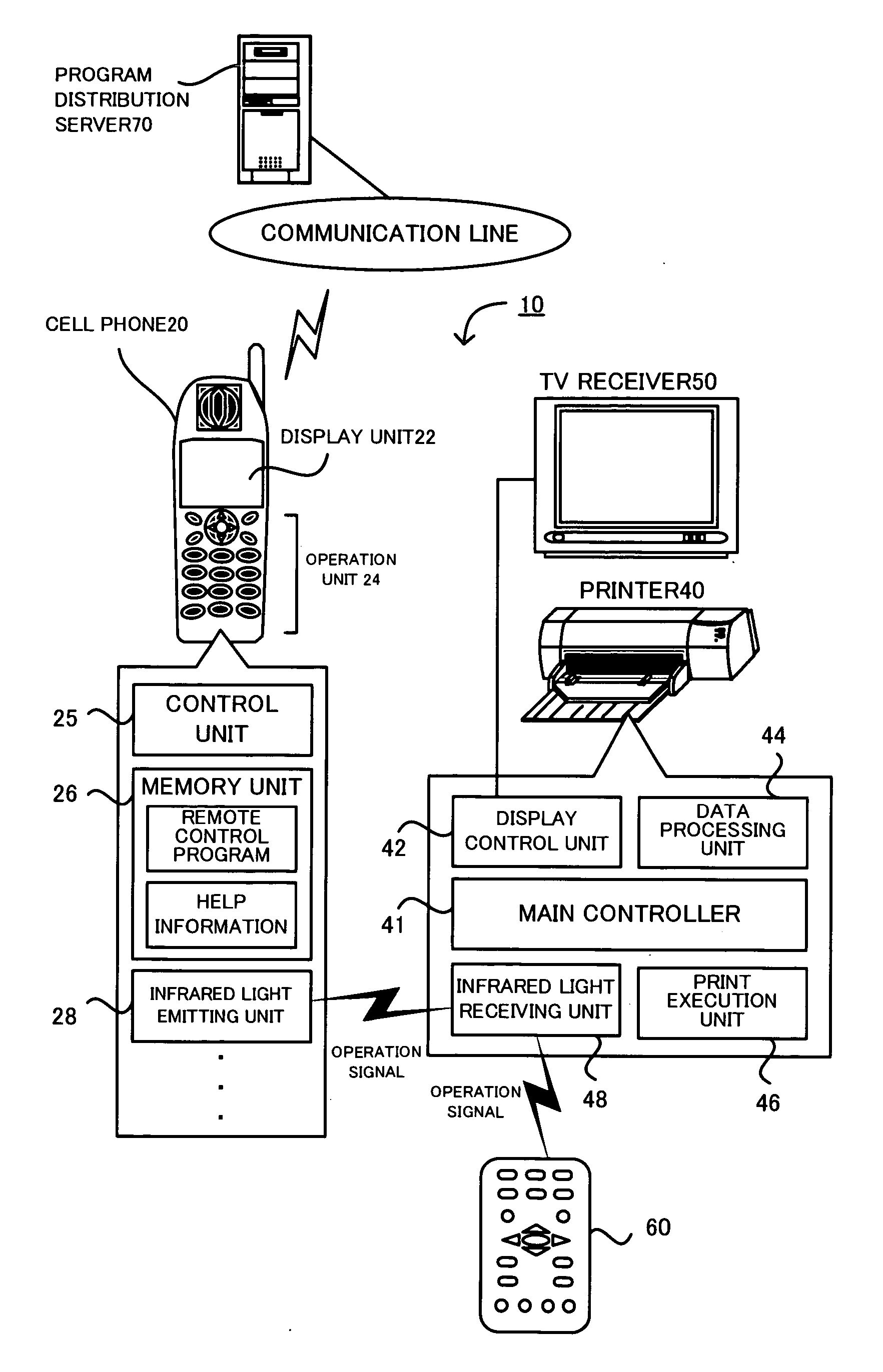
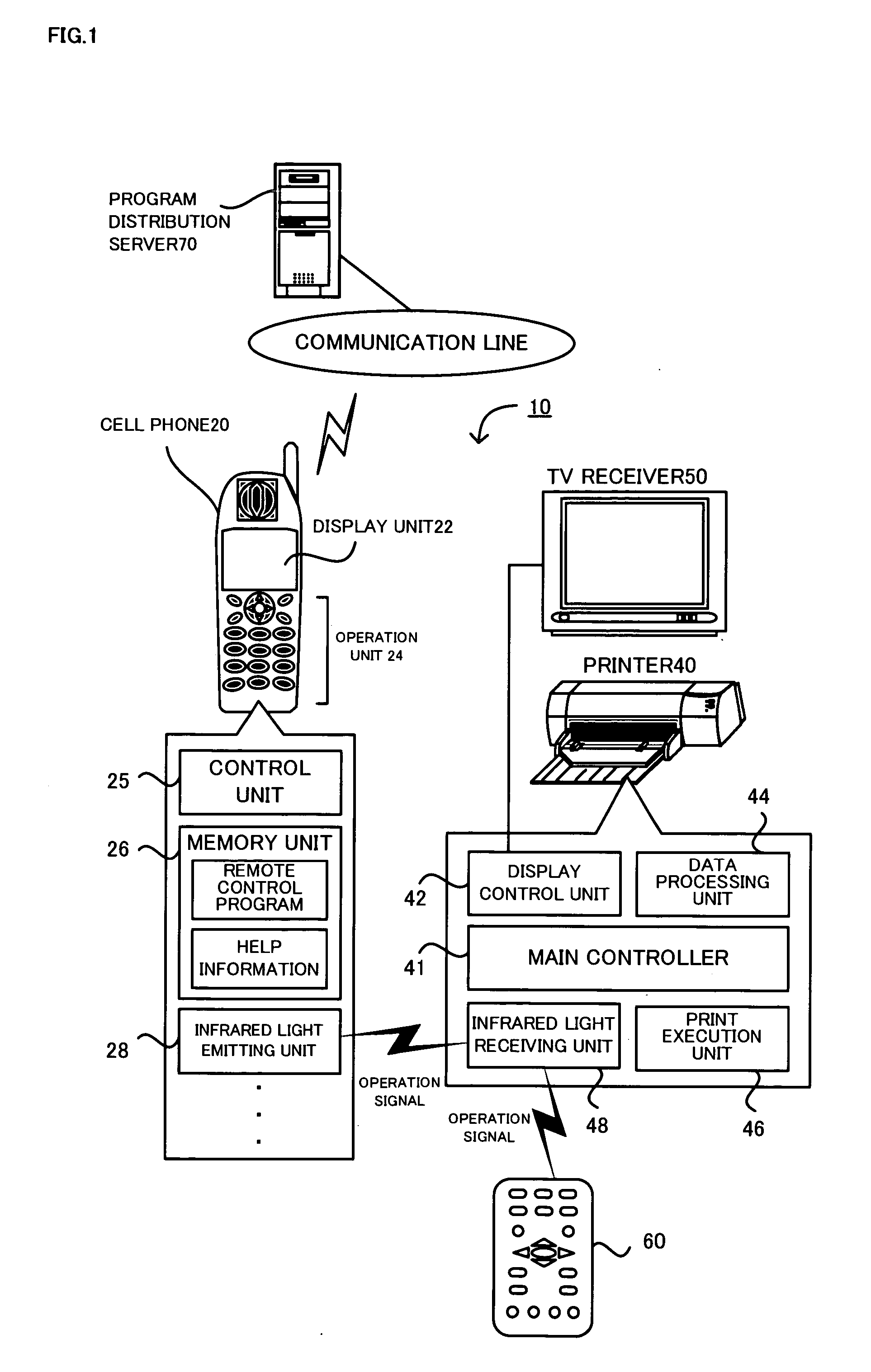
[0038] One mode of carrying out the invention is described below as a preferred embodiment. FIG. 1 schematically illustrates the configuration of a remote control system 10 including a cell phone 20 with a program for remote control installed therein as a program for an operation signal transmitter in one embodiment of the invention. As illustrated, the remote control system 10 includes the cell phone 20 that establishes voice and data communication via a predetermined communication line and a printer 40 that prints letters, characters, and images on paper. The printer 40 is remotely controlled in response to operation signals (remote control signals) sent from the cell phone 20.

[0039] The cell phone 20 includes a display unit 22 that displays letters, characters, and images, an operation unit 24 that includes multiple buttons and receives entries of a user's operations, a control unit 25 that controls the whole cell phone 20, a memory unit 26 that stores data, an infrared light em...


PUM


Abstract

A remote control program installed in a cell phone is activated to read a window number allocated to an operation window output and displayed on a TV receiver from a memory unit of the cell phone and to display corresponding help information on a display unit of the cell phone (steps S100 and S110). In response to the user's manipulation of one of buttons on an operation unit of the cell phone, the remote control program displays button function information representing the functions of the respective buttons on the operation unit, while converting an input signal into an operation signal and sending the converted operation signal together with the window number (steps S120 to S150).

Description

BACKGROUND OF THE INVENTION [0001] 1. Field of the Invention [0002] The present invention relates to a mobile terminal-based remote control technique. More specifically the invention pertains to a storage medium for storing a program, which is to be installed in a mobile terminal for remote controlling a specified device, where the mobile terminal includes a display unit that displays letters, characters, and images and an operation unit that receives an entry of a user's operation, has a predetermined wireless communication function, and is capable of establishing communication via a predetermined communication line. The invention also pertains to a server computer for distributing such a program, as well as to a remote control system with the mobile terminal and a corresponding remote control method using the mobile terminal. [0003] 2. Description of the Prior Art [0004] One proposed operation signal transmitter is a remote control that remote controls a TV receiver and other devi...

Claims


Application Information

Patent Timeline
Patent Type & Authority Applications(United States)
IPC IPC(8): G06F3/02H04M1/72415G06F3/00G06F3/048G06F3/0487G06F3/0489G06F13/00G06Q10/00G06Q50/00H04B7/00H04M1/00H04M11/00H04N5/00H04Q7/20H04Q9/00
CPCH04M1/72533G08C2201/93G08C2201/34H04M2250/56H04M1/72415
Inventor TOKUHASHI, HIDEKAZU
Owner SEIKO EPSON CORP
Why Eureka
Try Eureka