Bicycle derailleur

Inactive Publication Date: 2005-09-01
SHIMANO INC
View PDF6 Cites 10 Cited by
  • Summary
  • Abstract
  • Description
  • Claims
  • Application Information

AI Technical Summary

Benefits of technology

[0010] In accordance with this embodiment, because the chain return section is formed at the portion close to the tension pulley on the inner plate as a protrusion, so that the clearance from the chain at this portion is narrower than at other portions, even when the chain falls off from the tension pulley, when the chain is continuously rotated by means of pedaling action, the link component of the chain is pressed by the chain return section; consequently, the chain can be returned to the tension pulley more easily. Therefore, even when the chain has fallen off from the tension pulley, the chain can be returned to the tension pulley by means of pedaling action.
[0011] Preferably, the chain return section is structured by means of a protrusion which is formed thicker than at other portions at the aforementioned position on the inner plate. More preferably, the chain return section is structured simply by forming a protrusion on the inner plate. Such a chain return section can be obtained at low cost.
[0012] In additional preferred embodiments, the inner plate is equipped with two arms, which extend from the position onto which the tension pulley is mounted, and an arch, which has a circular-arc shape and which connects the arms; and a chain return section, which is installed on the circular-arc shaped arch. Preferably, the chain return section is installed on the circular-arc shaped arch, such that the area which comes into contact with the chain becomes larger; therefore, the chain can be returned to the tension pulley more easily.
[0013] In other preferred embodiments, the arch is positioned in the area extending downward from and rearward of the position at which the tension pulley is mounted, and the chain return section is formed at the position which becomes the do

Problems solved by technology

Such re-detailing procedure is cumbersome.
Especially in the midst

Method used


Image

  • Bicycle derailleur
  • Bicycle derailleur
  • Bicycle derailleur

Examples


Embodiment Construction

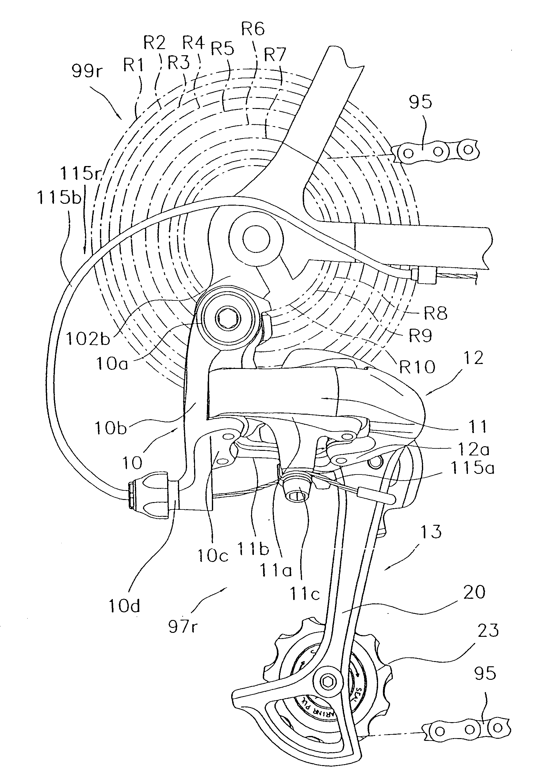
[0007] In accordance with a preferred embodiment of the present invention, a Bicycle rear derailleur is provided which is mounted onto a bicycle frame in order to selectively derail the chain resting upon any of a multiple number of sprockets mounted onto a rear hub axis, and which is equipped with a base component, a link mechanism, a movable component, an outer plate, an inner plate, a guide pulley, and a tension pulley. The base component is mounted onto the frame. One end of the link mechanism is mounted onto the base component. The movable component is mounted onto the other end of the link mechanism, and can be relatively displaced from the base component. The outer plate is mounted unto the movable component so as to undulate like a see-saw. The inner plate is installed so as to face the outer plate. The guide pulley is mounted onto a portion on one edge of the plates, between the plates, so as to freely rotate and freely move in the axial direction, and can be engaged by mea...


PUM


Abstract

An apparatus for achieving the return of a chain to a rear derailleur tension pulley more easily by means of pedaling action when the chain falls off from the tension pulley is provided. The rear derailleur is equipped with a base component, a link mechanism, a movable component, Outer Plate 20, Inner Plate 21, Guide Pulley 22, Tension Pulley 23, and Chain Return Section 32. The base component is a component which is mounted on the frame. The link mechanism is a mechanism of which one end is mounted on the base component. The movable component is a component which is mounted on the other end of the link mechanism, and which can be relatively displaced from the base component. The outer plate is a component which is mounted on the movable component so as to undulate like a see-saw. The inner plate is a component which is installed so as to face the outer plate. The guide pulley is a pulley which is mounted onto a portion on one edge of the plates, between the plates, so as to freely rotate and move in the axial direction, and which can be engaged with the chain. The tension pulley is a pulley which can be engaged with the chain, and is mounted onto a portion on the other edge of the plates, between the plates, so as to freely rotate. The chain return section is installed at a position on the inner plate which is proximal to the position at which the tension pulley is mounted, in a manner so that the clearance from the chain at this position is narrower as compared to the clearance at other positions.

Description

FIELD OF THE INVENTION [0001] The present invention relates to a derailleur, in particular to a bicycle rear derailleur which is mounted onto a bicycle frame so as to selectively derail the chain resting upon any of a multiple number of sprockets mounted onto a rear hub axis. BACKGROUND OF THE INVENTION [0002] An externally-mounted speed changing device, or rear derailleur, is mounted onto a bicycle, especially onto a sports-type road racer or mountain bike. Such rear derailleur is equipped with a base component, which is mounted on the frame; a link mechanism, one end of which is mounted on the base component; a movable component, which is mounted on the other end of the link mechanism, and which can be relatively displaced from the aforementioned base component; and a chain guide, which is mounted on the movable component so as to undulate like a see-saw. The chain guide functions to transfer the chain, so as to derail the chain upon any of the rear sprockets. The chain guide is e...

Claims


Application Information

Patent Timeline
IPC IPC(8): B62M9/1242B62M9/126
CPCB62M9/126B62M9/1242
Inventor ONOGI, TAKUMIADACHI, TAKASHIKINOSE, YOSHIHIRO
Owner SHIMANO INC
Why Eureka
Try Eureka