Computer program for designing treating member and system for providing service using the program

a computer program and design technology, applied in the field of program for designing a treating member, can solve the problems of inability to meet arbitrary chemical treatment process, complicated operation of various chemical treatment processes, and inability to program or system to provide microstructures in compliance,

Inactive Publication Date: 2005-09-01
HITACHI LTD
View PDF8 Cites 7 Cited by
  • Summary
  • Abstract
  • Description
  • Claims
  • Application Information

AI Technical Summary

Problems solved by technology

Various processes have been developed, and these various chemical treatment processes require complicated operations; generally, individual treatment steps are carried out by hand sequentially in such a way that samples and reagents are placed in glass flasks and test tubes.
In the aforementioned WO 00 / 78455, there is disclosed a technique in which for a particular treatment process of gene extraction, a sequence of operations are completely automated by making liquids flow by exerting centrifugal force through rotary driving; however, this technique cannot meet arbitrary chemical treatment processes.
However, there has not yet been known a program or a system which provides microstructures in compliance with an arbitrary chemical treatment process.

Method used


Image

  • Computer program for designing treating member and system for providing service using the program
  • Computer program for designing treating member and system for providing service using the program
  • Computer program for designing treating member and system for providing service using the program

Examples


first best embodiment

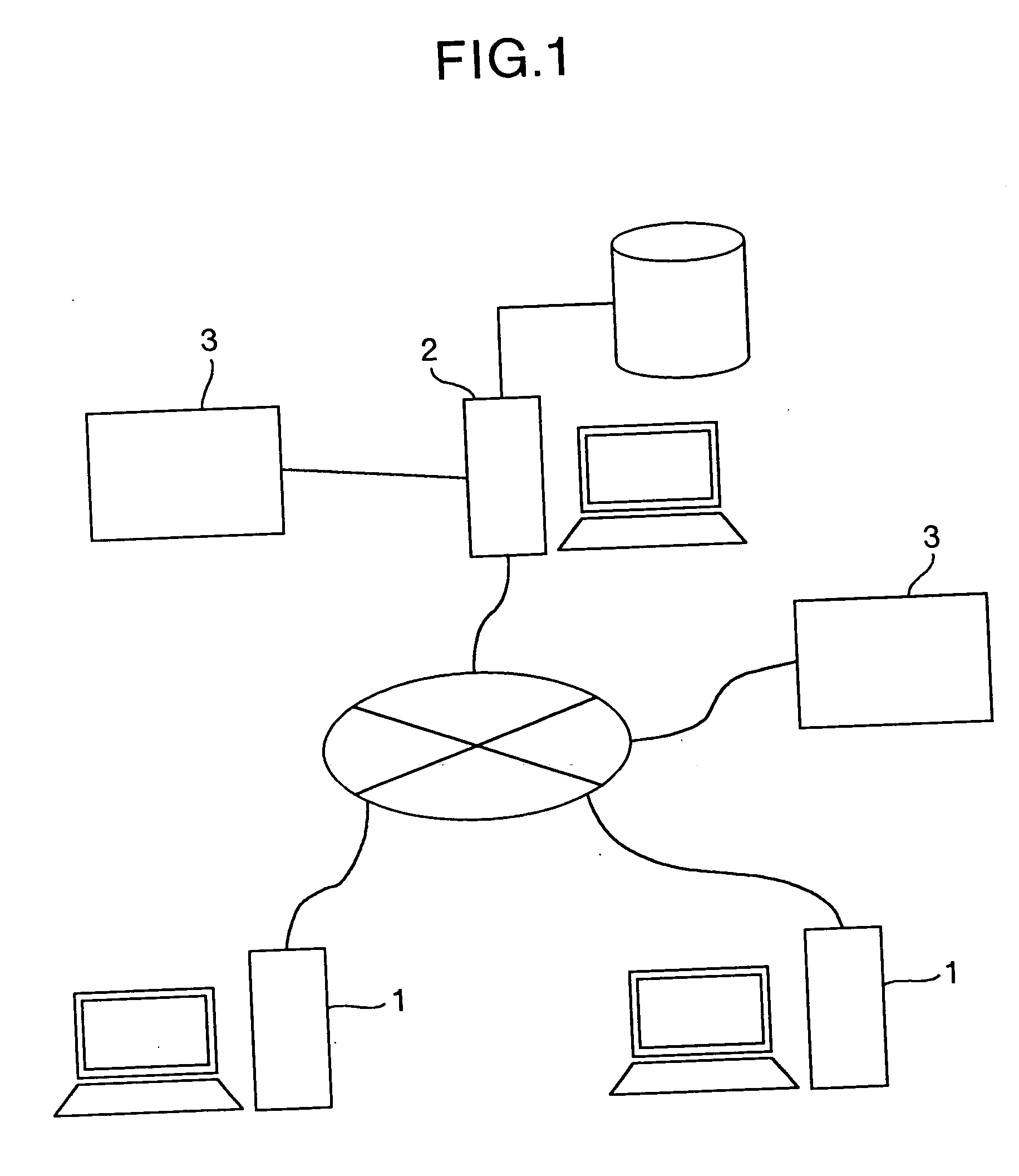
[0022] As shown in FIG. 1, the system for designing the treating member according to the present invention includes a user terminal 1 belonging to the system user side, a provision terminal 2 for designing a flow path in the treating member to be used in a chemical or other treatment process, and a treating-member fabrication unit 3 for fabricating the treating member. In the present system, the user terminal 1 and the provision terminal 2 are connected to each other through the intermediary of communication network such as Internet and intranet, and can exchange various types of data with each other. Incidentally, in the present system, the unit 3 for fabricating the treating member may be directly connected to the provision terminal 2, or may be connected to the provision terminal 2 through the intermediary of communication networks in a communicatable manner.

[0023] In the present system, a treating member to actualize the treatment sequence desired by a user of the system is des...

second best embodiment

[0073] In the aforementioned first best embodiment, based on the piece of input information entered by the system user, the design of the treating member is carried out on the provision terminal side; however, the technical scope of the present invention is not limited to the first best embodiment.

[0074] In other words, as a second best embodiment applied with the present invention, the system for designing a treating member may be a system in which a piece of design information about the treating member 10 is acquired on the user terminal 1 belonging to the system user side, and the acquired piece of design information is output toward the provision terminal. In this case, a program for designing a treating member is installed in the user terminal 1, and steps 1 up to 3 shown in FIG. 4 are executed on the user terminal 1. In this connection, the program for designing a treating member may be arranged to be downloaded into the user terminal 1 after the system user have received cer...


PUM

PropertyMeasurementUnit
physical propertyaaaaaaaaaa
shapeaaaaaaaaaa
specific gravityaaaaaaaaaa

Abstract

A computer program embodied on a computer readable medium for designing a treating member contains a first code segment adapted to acquiring a piece of input information containing a treatment sequence; and a second code segment adapted to designing a flow path along which a sample moves, based on the piece of input information.

Description

INCORPORATION BY REFERENCE [0001] The present application claims priority from Japanese application JP 2004-055354 filed on Feb. 27, 2004, the content of which is hereby incorporated by reference into this application. BACKGROUND OF THE INVENTION [0002] The present invention relates to a program for designing a treating member to be used when treatments such as chemical reactions are conducted as an automated process, and a system for providing a service to design a treating member using the program concerned. [0003] In general, a chemical treatment process is constituted with a sequence of individual treatments referred to as unit chemical operations such as centrifugal separation and mixing / reaction. Various processes have been developed, and these various chemical treatment processes require complicated operations; generally, individual treatment steps are carried out by hand sequentially in such a way that samples and reagents are placed in glass flasks and test tubes. However, ...

Claims


Application Information

Patent Timeline
Patent Type & Authority Applications(United States)
IPC IPC(8): B01L3/00G06F17/50G16H20/10G01N37/00
CPCB01L3/5027G06Q50/24G06F17/50G06F30/00G16H20/10
Inventor MIYAKE, RYOOTAGURO, TOSHIOOKADA, RYOJISASAKI, NAOYA
Owner HITACHI LTD
Why Eureka
Try Eureka