Web buffering device

a buffering device and web technology, applied in the field of web buffering devices, can solve the problems of complex and costly coordination control, web material susceptible to disturbances from drafts, etc., and achieve the effect of convenient control and convenient interfa

Inactive Publication Date: 2005-09-08
DILO MASCHF OSKAR
View PDF9 Cites 9 Cited by
  • Summary
  • Abstract
  • Description
  • Claims
  • Application Information

AI Technical Summary

Benefits of technology

[0007] Another object of the invention is to provide web buffering apparatus which is easily controlled.
[0008] Another object of the invention is to provide web buffering apparatus which interfaces more easily with certain web processing apparatus.
[0009] Still another object of the invention is to provide web buffering apparatus which protects the web material along its path through the buffering apparatus.
[0010] Yet another object if the invention is to provide web buffering apparatus which is structurally simple.

Problems solved by technology

Such coordinated control is both complex and costly.
Further, along some portions of the web path from the infeed from the web producer to the outfeed to the web processing apparatus, the web material is not fully clamped, leaving the web material susceptible to disturbances from drafts.

Method used


Image

  • Web buffering device
  • Web buffering device
  • Web buffering device

Examples


Embodiment Construction

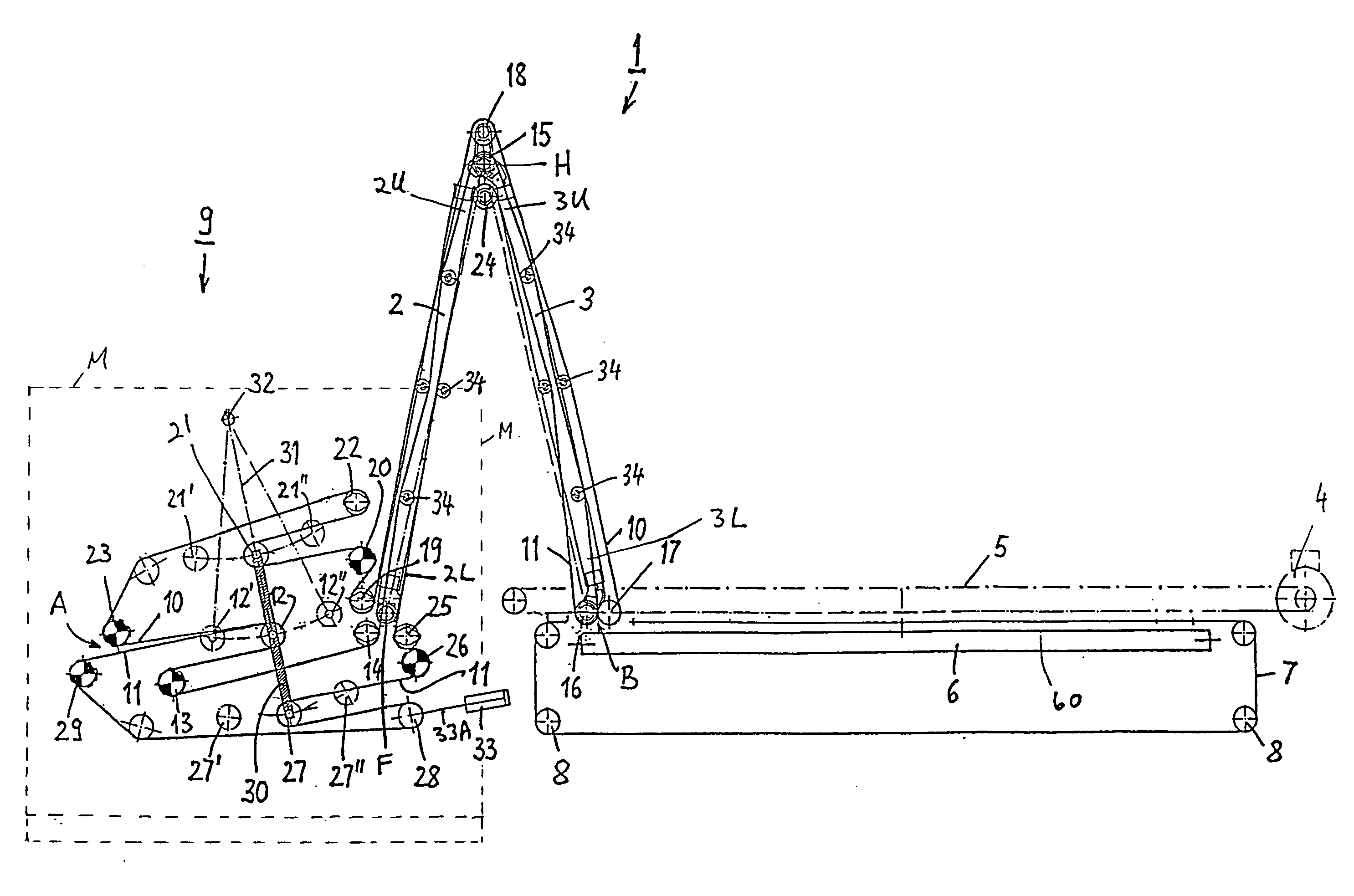
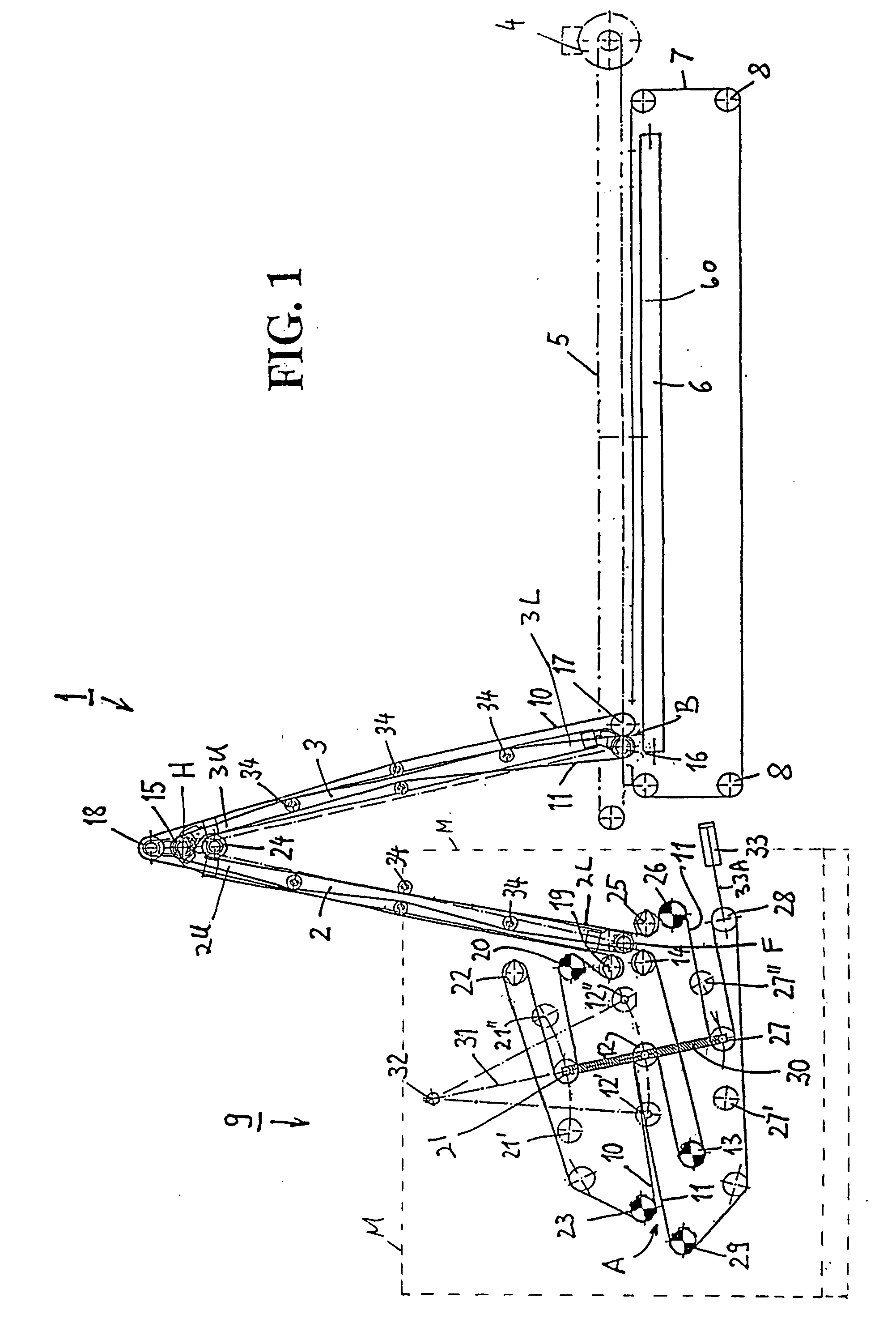
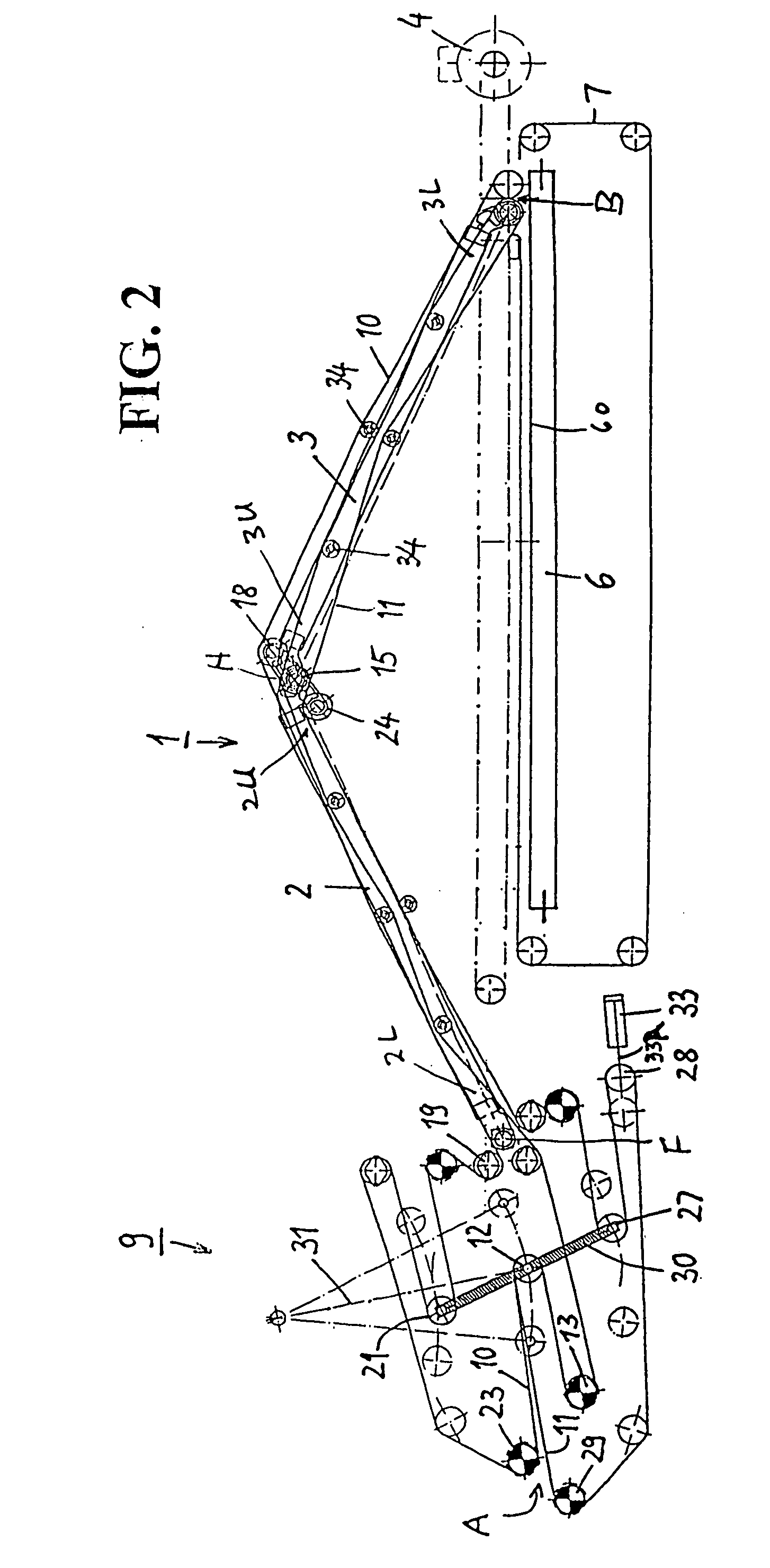
[0022]FIG. 1 shows a first arm 2, also designated as a supply arm, and a second arm 3, also designated as a layering arm, of a camel back cross lapper 1 for fleece production. Supply arm 2 is pivotally supported at its lower end 2L in a machine stand M (shown in dotted line format on FIG. 1). A hinge H at the upper end 2U of the supply arm 2 and the upper end 3U of layering arm 3 provides hinging movement between arms 2 and 3. The lower end 3L of arm layering 3 is capable of being transversely moved above an output conveyor 60 by means of a stationary drive 4 and a toothed belt 5, with a deflecting roller 6 of output conveyor 60 being schematically shown in the drawing. (The apparatus shown in FIGS. 1 and 2 contain numerous deflecting and drive rollers which will be specified primarily by reference number only and not by differentiating names.) Output conveyor 60 extends perpendicularly to the direction of movement of lower end 3L of layering arm 3 and around deflecting roller 6. A ...


PUM

PropertyMeasurementUnit
laying widthaaaaaaaaaa
lengthaaaaaaaaaa
lengthaaaaaaaaaa

Abstract

Apparatus for variably buffering a web material, the apparatus having two endless transport belts including feed sections in which the belts are juxtaposed, and return sections, the feed and return sections being of varying lengths. In the feed sections, the belts move through a U-shaped path portion, commonly guided over a deflecting roller. In the return sections, the belts are guided through U-shaped path portions extending opposite to the U-shaped path portion of the feed sections, each belt wrapping separate deflecting rollers. The three deflecting rollers are rotatably supported on a common mounting frame movably held in a machine stand for compensated length variation of the feed and return portions.

Description

RELATED APPLICATION [0001] This application claims the benefit of EP 04 005 460.3, filed on Mar. 8, 2004, the contents of which are incorporated herein. FIELD OF THE INVENTION [0002] This invention is related generally to the field of web handling machinery. More particularly, the invention relates to the control of the speed of web material in web handling machinery in situations in which the relative speeds of different portions of the web fluctuate with respect to each other. BACKGROUND OF THE INVENTION [0003] U.S. Pat. No. 5,590,442 describes web storage apparatus for non-woven fabrics. The web storage apparatus is located between a web producer and web processing apparatus, e.g., between a carding machine, operating at constant output speed, and fabric layering apparatus, operating at rhythmically variable take-up speeds. In such fabric layering apparatus, the transport speed of the web within the machine changes during transport depending on the movements of the layering carri...

Claims


Application Information

Patent Timeline
Patent Type & Authority Applications(United States)
IPC IPC(8): D01G25/00
CPCD01G25/00
Inventor LEGER, JOACHIM
Owner DILO MASCHF OSKAR
Why Eureka
Try Eureka