
Anti-theft device for equipment

Inactive Publication Date: 2005-09-08
MATHERS ROBERT
View PDF14 Cites 2 Cited by
  • Summary
  • Abstract
  • Description
  • Claims
  • Application Information

AI Technical Summary

Benefits of technology

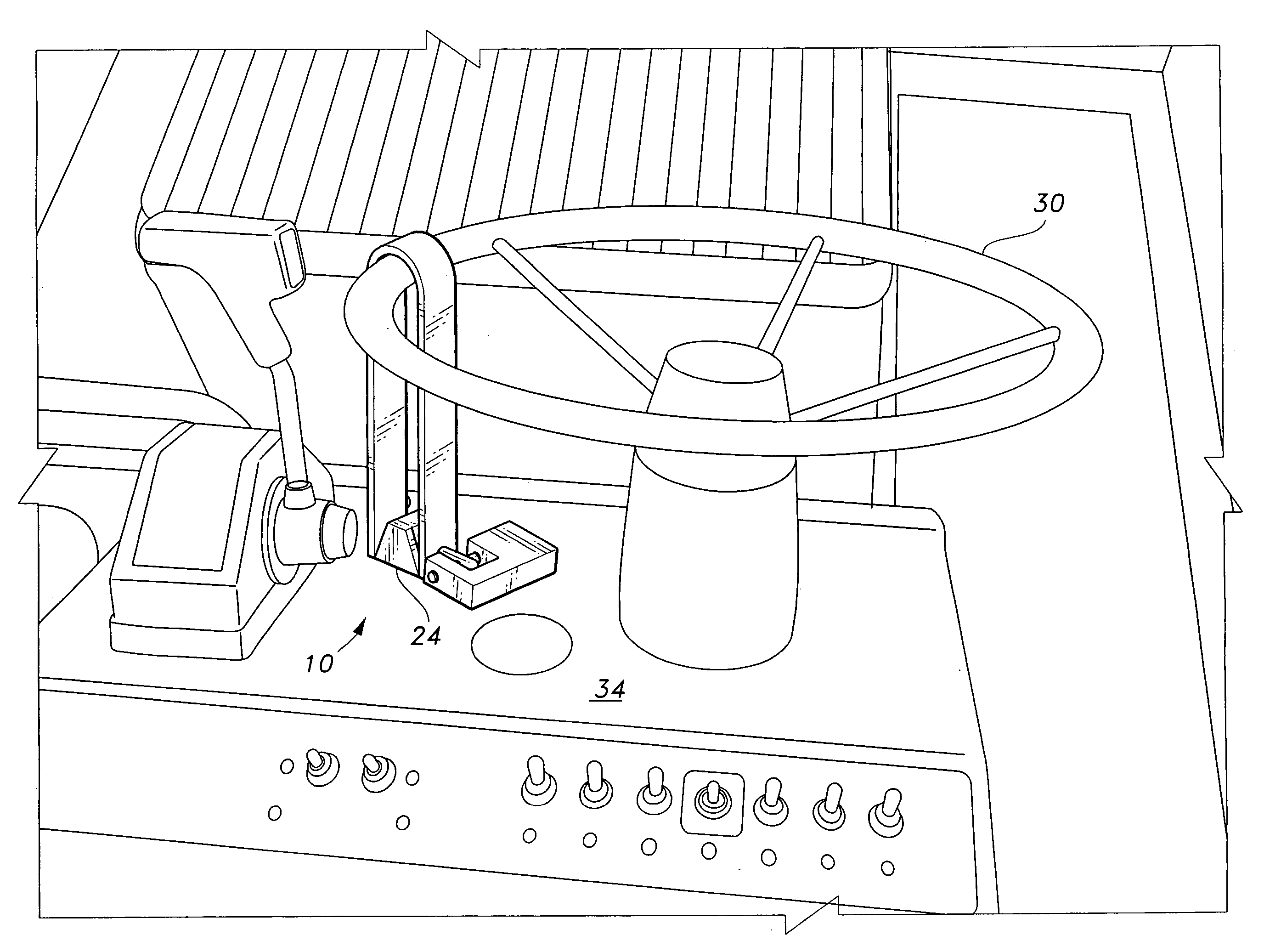
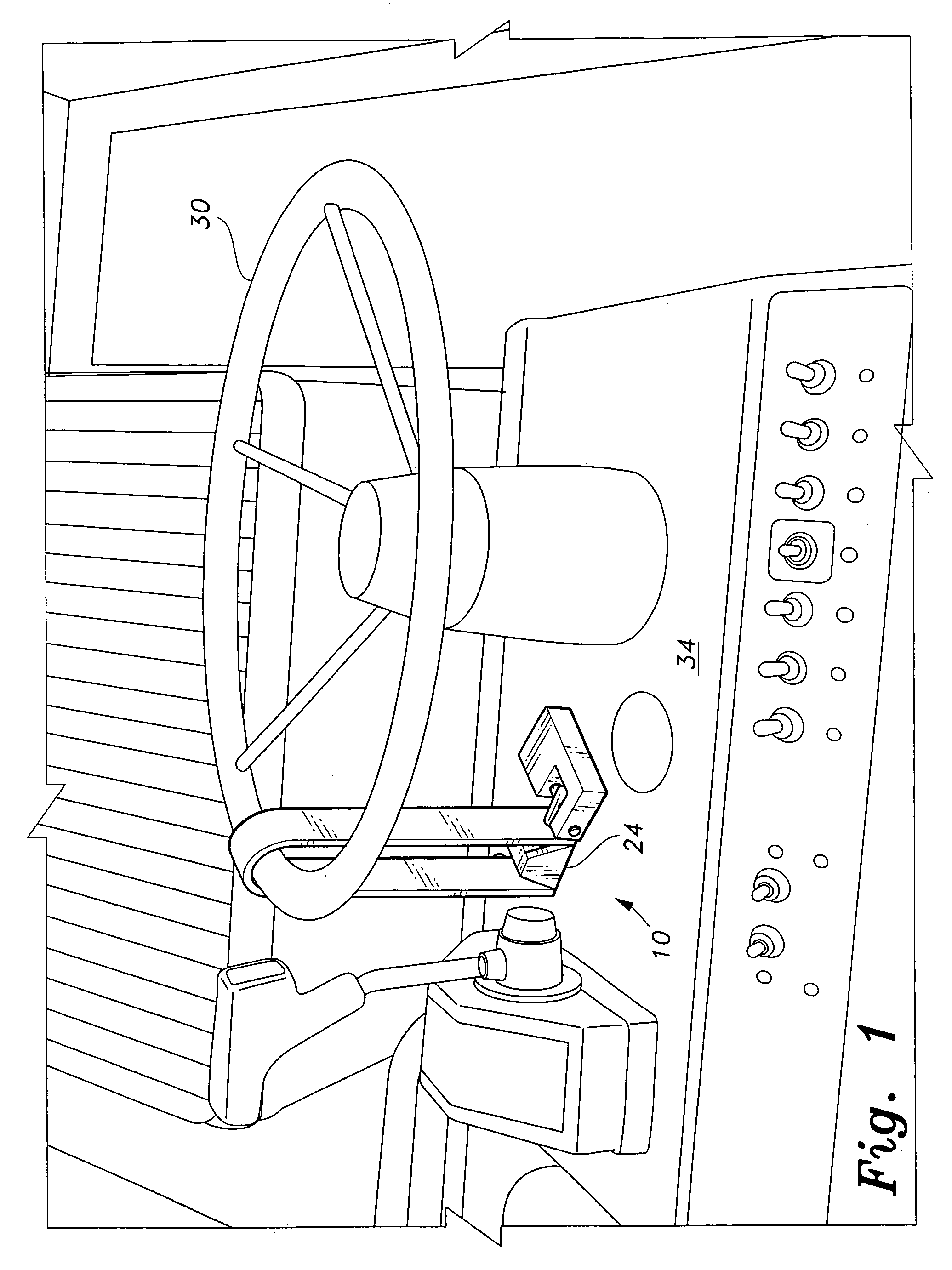
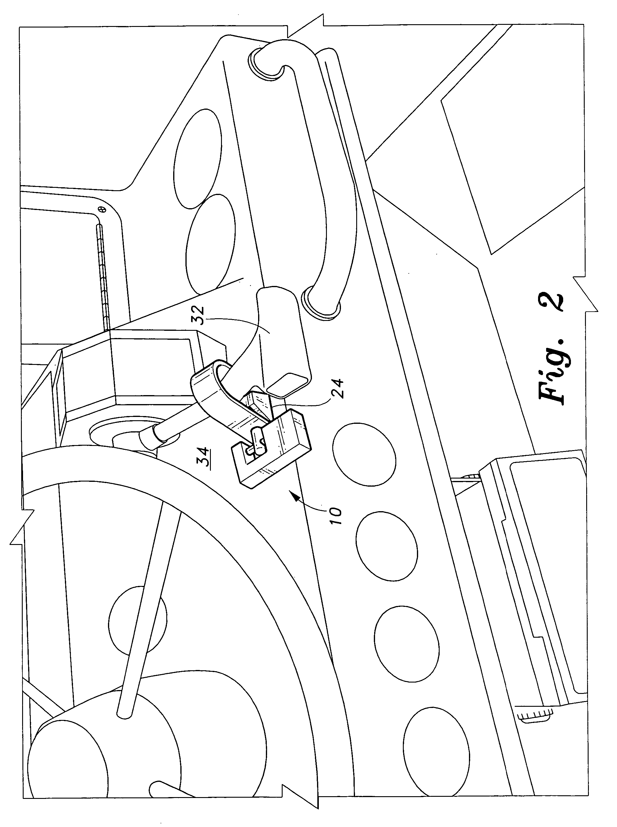
[0006] The instant invention is an anti-theft device for deterring unauthorized operation of designated equipment control adjuncts. The device is adapted to secure the designated control to prevent manipulation thereof. Consisting of only a clevis pin, a clevis and a padlock, the device is compact in design and easy to use. A uniquely designed hasp is employed to accomplish proper attachment of the anti-theft device. The hasp is secured directly to a permanent planar surface of the equipment. The clevis pin and clevis are removable from the hasp and can be conveniently stored or transported to be used elsewhere.
[0007] Accordingly, the instant invention presents an anti-theft device, which device is fabricated from rugged material and provides improved elements and arrangements thereof for the purposes described which are inexpensive, dependable and fully effective in accomplishing their intended purposes.

Problems solved by technology

Theft and / or unauthorized use of outdoor recreational equipment, marine, construction and lawn gear is a major problem for the owners.
Equipment that must be left outdoors has no adequate means of theft protection.
Aside from the temporary or permanent loss of the equipment or gear, the cost of repairs and subsequent rise in insurance rates can create a major financial burden.
However, none of the above inventions and patents, taken either singly or in combination, is seen to disclose an anti-theft device as will be subsequently described and claimed herein.

Method used


Image

  • Anti-theft device for equipment
  • Anti-theft device for equipment
  • Anti-theft device for equipment

Examples


first embodiment

[0018] Attention is first directed to FIG. 6, which shows the anti-theft device of the instant invention generally at 10. The anti-theft device 10 comprises a U-shaped clevis 20, a clevis pin 22, a hasp 24 and a padlock 26. At its distal end 22a, pin 22 terminates in an L-shaped configuration. Openings 20a are formed through the clevis 20 adjacent each end thereof. An opening 22b is formed through the pin adjacent the proximate end thereof. Hasp 24 is adapted to have its base 24a securely attached to a vehicle substrate. The attachment may be accomplished in any convenient manner (screws, rivets, pins, welds, etc.). Hasp 24 is solid except for an opening 24b formed therethrough.

second embodiment

[0019] the anti-theft device is illustrated in FIGS. 7 and 8. The U-shaped clevis 70 and lock 72 are permanently attached. The attachment can be effected in any conventional manner (screws, rivets, welds, etc.). Lock 72 is provided with an opening 72a therein, which opening is in axial alignment with openings 70a in the U-shaped clevis member. Clevis pin 74 is adapted for insertion through a first opening 70a, hasp 24, a second opening 70a and into opening 72a in lock 72. Clevis pin 74 is formed with a cap at its distal end. A lock notch is positioned adjacent the proximate end. A key 76 is insertable into lock 72 to secure the clevis pin 74.

[0020] The clevis member, clevis pin and hasp can be fabricated from a variety durable metal stock having chemical and / or corrosion resistant coatings. However, it is recognized that a plastic material may be utilized if suitable.

[0021] The anti-theft device of the present invention is effective in almost limitless situations to effectively det...


PUM


Abstract

An anti-theft device for deterring unauthorized operation of a designated vehicle control adjunct. The device is adapted to secure the designated control to prevent manipulation thereof. The device includes a clevis pin, a clevis and a padlock and a hasp. The hasp is secured directly to a permanent planar surface of the vehicle.

Description

CROSS-REFERENCE TO RELATED APPLIATIONS [0001] This application is a continuation-in-part of prior application Ser. No. 10 / 938,547 filed Sep. 13, 2004, which is a continuation-in-part of prior application Ser. No. 10 / 441,075 filed May 20, 2003 now U.S. Pat. No. 6,789,405 B1.BACKGROUND OF THE INVENTION [0002] 1. Field of the Invention [0003] The present invention generally relates to security devices. More specifically, the present invention is drawn to an anti-theft device for securing vehicle operating controls and personal equipment. [0004] 2. Description of the Related Art [0005] Theft and / or unauthorized use of outdoor recreational equipment, marine, construction and lawn gear is a major problem for the owners. Equipment that must be left outdoors has no adequate means of theft protection. Aside from the temporary or permanent loss of the equipment or gear, the cost of repairs and subsequent rise in insurance rates can create a major financial burden. There are many patents in th...

Claims


Application Information

Patent Timeline
IPC IPC(8): E05B73/00
CPCE05B73/0076Y10T70/40Y10T70/409Y10T70/5009Y10T70/5765Y10T70/5867Y10T70/5889
Inventor MATHERS, ROBERT
Owner MATHERS ROBERT
Learn More