Ratiometric stud sensing

a technology of studs and sensing devices, applied in the field of electronic sensors, can solve the problems of reducing the ability to accurately determine the centerline of studs, affecting the accuracy of studs, so as to reduce the effect of an unknown thickness of the member and the effect of effective capacitan

Active Publication Date: 2005-09-08
ZIRCON
View PDF43 Cites 63 Cited by
  • Summary
  • Abstract
  • Description
  • Claims
  • Application Information

AI Technical Summary

Benefits of technology

[0011] An apparatus and method for determining a feature of a structure while reducing effects of an unknown thickness of the member located behind a surface are provided. The feature may be a centerline and / or an edge of an object or member, such as a stud or joist. The feature may also be an edge of a gap or discontinuity of the structure. The sensor apparatus includes a plurality of capacitive plates. The sensor may also include circuitry to sense an effective capacitance created by a plate, the covering and objects behind the covering. The sensor may compute a ratio between the capacitance measurements of a pair of the plates. A ratio of approximately one may indicate a centerline of a stud or joist or similar member. A ratio in a predetermined range may indicate an edge of a stud or joist.

Problems solved by technology

Finding studs is a typical problem for building repairs, picture hanging, etc.
While this procedure is effective in determining the centerline of a stud, significant errors in determining the location of the stud's edges can occur.
The ballooning may be asymmetric due to electrical wires, metallic pipes and other objects in close proximity to the stud, which in turn may lead to a reduced the ability to accurately determine a stud's centerline.
Unfortunately, using a dual sensitivity control only partially minimizes the ballooning effect.
The above methods, which use electronic wall stud sensors, are unable to reliably and accurately sense an edge of a stud (or other structural member) through surfaces that are thicker than 38 mm (1½ inches).
Additionally, these sensors, if overly sensitive, falsely indicate the presence of non-existing studs.
Therefore, known sensors have disadvantages.

Method used


Image

  • Ratiometric stud sensing
  • Ratiometric stud sensing
  • Ratiometric stud sensing

Examples


Embodiment Construction

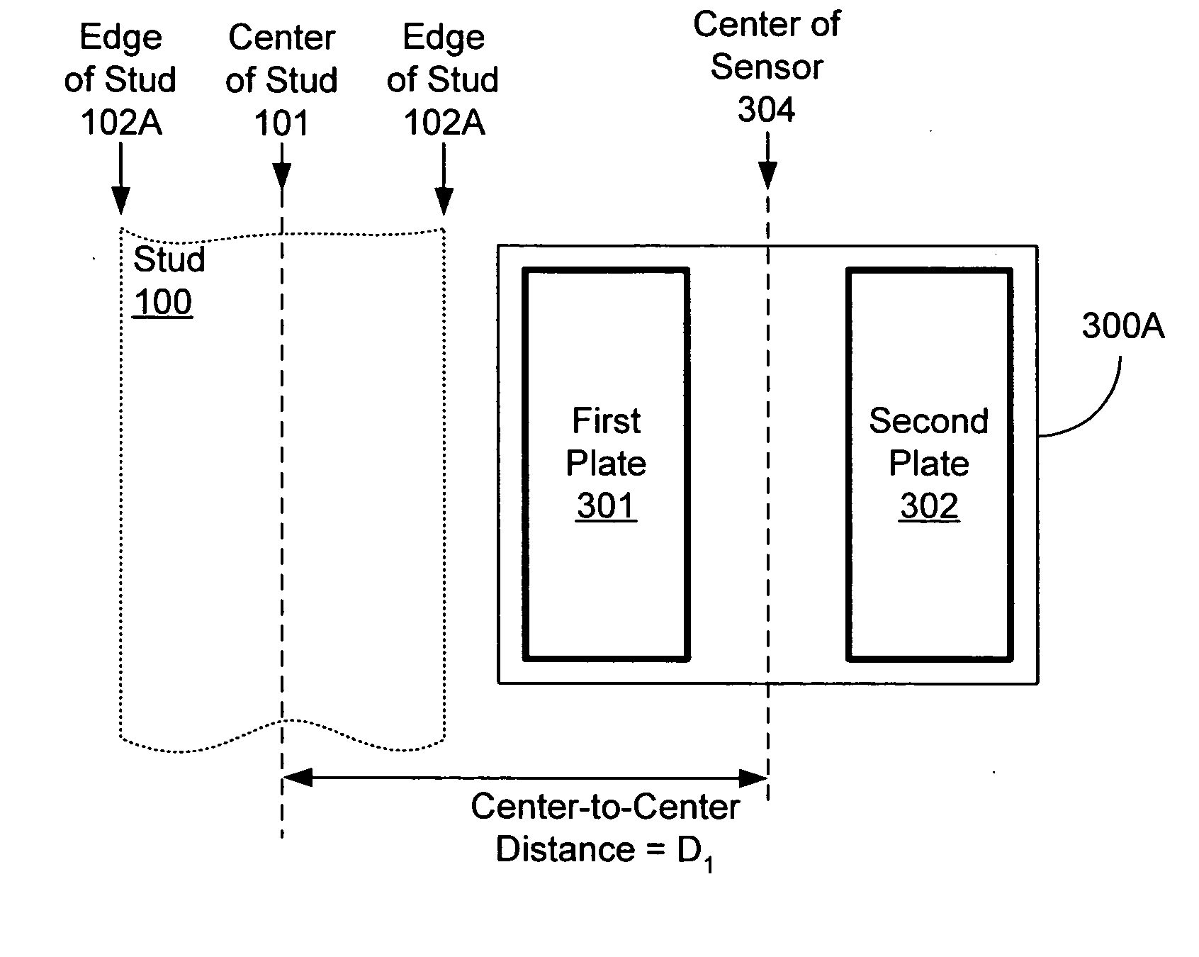
[0038] A ratiometric capacitive sensor may use capacitance measurements from multiple conductive plates to determine the presence of objects, such as studs and joists, hidden behind a covering surface such as a wall, floor, ceiling, etc. In some embodiments, a ratiometric capacitive sensor includes two conductive plates. Each conductive plate acts as part of a separate capacitor. Circuitry coupled to each plate measures an effective change in capacity of the separate capacitors, which is effected by the density of material in close proximity to the plates. As a result, the combination of a wall or other surface covering and an underlying stud or other member has a larger capacitance than a wall covering alone without a stud. A capacitance measurement may be taken from each plate. The capacitance measurement from one plate may then be compared to a capacitance measurement of another plate to determine boundaries and features of the materials in the vicinity of the plates.

[0039]FIG. ...


PUM


Abstract

A stud or joist sensor device and associated sensing method using a ratio of capacitance measurements from a plurality of capacitive sensing elements. The device locates a feature of an object or discontinuity behind a surface or wall, such as an edge and/or a center of a stud behind the surface, a joist under a floorboard, a gap behind sheetrock, a metal conductor behind a surface or the like. The device may be moved over a surface, thereby detecting changes in capacitance. The change in capacitance is due to the effective dielectric constant caused by the passage over an object such as a stud. When two capacitive sensing elements provide equivalent capacitance measures, the device is over a centerline of the stud. When a ratio of the capacitance measurements equals a transition ratio, the device is over an edge of the stud.

Description

BACKGROUND OF THE INVENTION [0001] 1. Field of the Invention [0002] This invention relates to an electronic sensor, and, in particular, to a sensor suitable for detecting the location of an object behind a variety of surfaces, including walls, floors and other non-electrically conductive structures. More specifically, the invention relates to an electronic sensor used to detect centerlines and edges of wall studs, floor joists, and the like. [0003] 2. Description of the Prior Art [0004] U.S. Pat. No. 4,464,622 entitled “Electronic wall stud sensor,” issued Aug. 7, 1984, and incorporated in its entirety by reference herein, discloses an electronic wall stud sensor particularly suitable for locating a stud positioned behind a wall surface. (A “stud” is a structural member of a building to which an interior wall surface such as wall board or paneling is affixed.) Typically in the U.S., “2-by-4” wooden studs are used in construction. Nominally, a 2-by-4 stud is 51 mm (2 inches) wide and...

Claims


Application Information

Patent Timeline
Patent Type & Authority Applications(United States)
IPC IPC(8): G01R27/26G01V3/08
CPCG01V3/088
Inventor MILLER, LAWRENCE F.
Owner ZIRCON
Why Eureka
Try Eureka