Display panel and display device

Inactive Publication Date: 2005-09-08
SHARP KK
View PDF10 Cites 26 Cited by
  • Summary
  • Abstract
  • Description
  • Claims
  • Application Information

AI Technical Summary

Benefits of technology

[0026] In view of the conventionally encountered problems described above, it is a first object of the present invention to provide a display device that can present a plurality of viewers with different images simultaneously with minimum waste of electric power. It is a second object of the present invention to provide a display panel and a display device that can present a plurality of viewers with different images simultaneously with minimum distortion in the displayed image.

Problems solved by technology

However, the display devices disclosed in the publications mentioned above are not designed to present information simultaneously to a plurality of viewers who want to view different kinds of information.
However, in a conventional dual-view display device, the display panel is driven with no consideration given to whether or not images need to be outputted in a plurality of directions at all.
Inconveniently, this results in a waste of electric power when the display device is viewed only from one direction.
Thus, even if the images to be outputted in the first and second viewing directions have different display frequencies (the frequencies at which image signals need to be fed in to maintain satisfactory display quality), it is not possible to set separate scanning frequencies (the frequencies at which the active elements need to be turned on) for the first and second pixels.
Thus, in a conventional dual-view display device, the pixels for displaying images having a lower display frequency are fed with overquality image signals, resulting in a waste of electric power in a source line drive circuit E2.
Likewise, when a viewer views the second image from the viewpoint D61, inconveniently, the second image appears to be distorted.

Method used


Image

  • Display panel and display device
  • Display panel and display device
  • Display panel and display device

Examples


second embodiment

[0075]FIG. 5 is an outline structure diagram (outline sectional view) showing, as a second embodiment, a dual-view display device embodying the present invention. As shown in this figure, the display device B of this embodiment has: a display panel B1 including first pixels “a” that output image light to be directed in the first viewing direction (image light for a viewer V1) and second pixels “b” that output image light to be directed in the second viewing direction (image light for a viewer V2); a source line drive circuit B2 that feeds image signals to the first and pixels “a” and “b”; a gate line drive circuit B3 that feeds scanning signals to the first and second pixels “a” and “b”; and an optical separator B4 (in this embodiment, a slit plate) that separates the image lights outputted from the first and second pixels “a” and “b” so that they are directed in the first and second directions, respectively.

[0076] In the display device B configured as described above, in the first...

third embodiment

[0117]FIG. 10 is an outline structure diagram (outline sectional view) showing, as a third embodiment, a dual-view display device embodying the present invention. As shown in this figure, the display device C of this embodiment has: a display panel C2; and a driver C1 that drives the pixels formed on the display panel C2. The display device C further has an optical separator C3 (in this embodiment, a slit plate) arranged on the front face of the display panel C2.

[0118] The display panel C2 has: first pixels that display a first image when viewed from a viewpoint C61 located at one side of the front face; and second pixels that display a second image when viewed from a viewpoint C62 located at the other side of the front face. In this embodiment, “one side” denotes the left-hand side of the display panel C2 as seen from in front, and the “other side” denotes the right-hand side. The first pixels include “a1” pixels C31, “a2” pixels C32, and “a3” pixels C33. The second pixels include...


PUM


Abstract

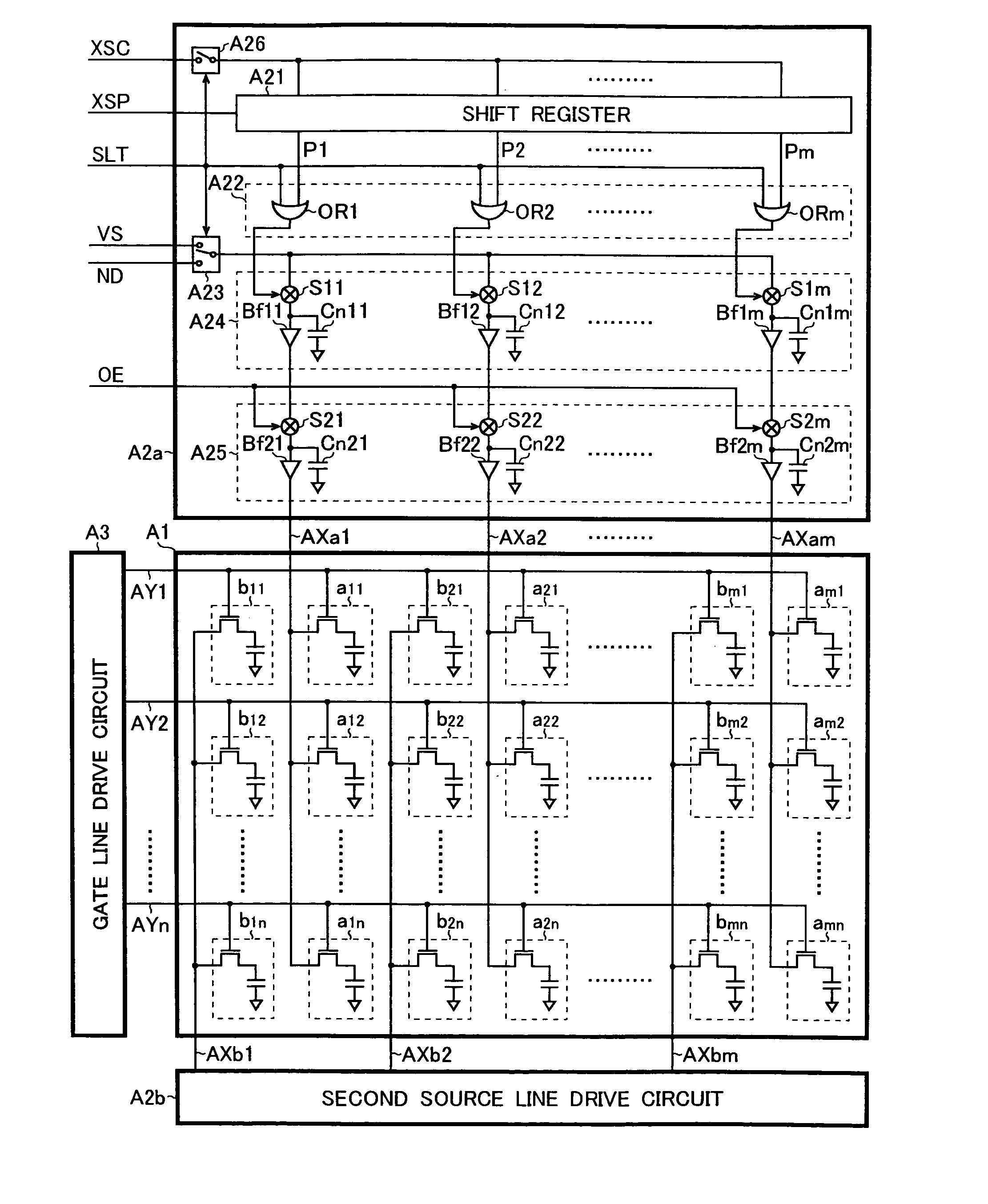
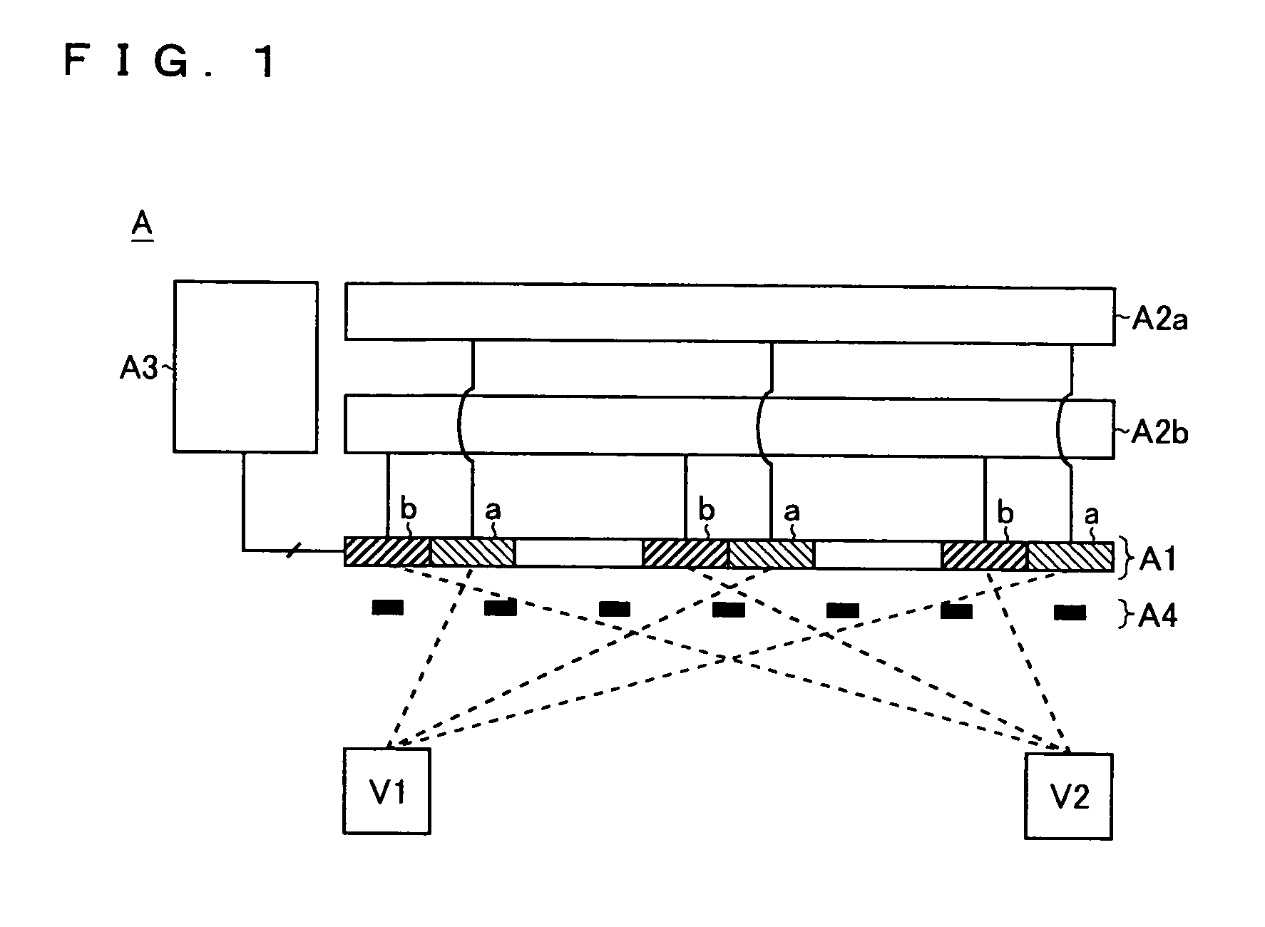
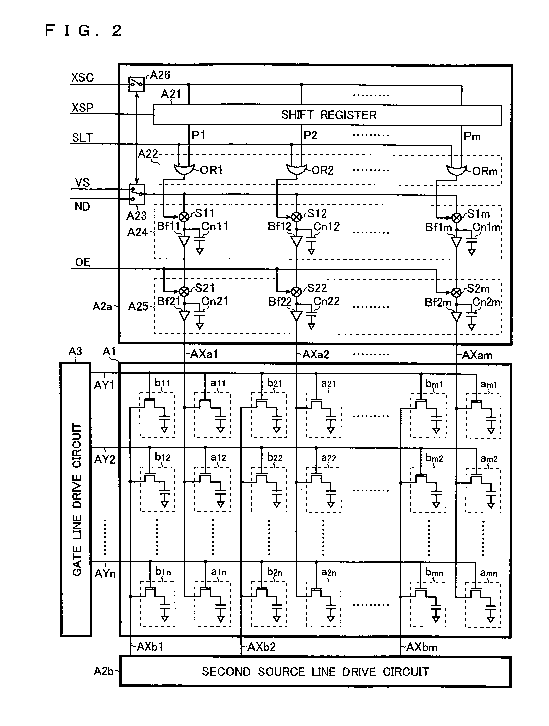
In a display device, at least one of a first drive circuit that feeds source signals to first pixels to be viewed from a first viewing direction and a second drive circuit that feeds source signals to second pixels to be viewed from a second viewing direction includes a shift register that generates a sampling pulse by shifting a start pulse in synchronism with a clock signal, a sampling circuit that samples an image signal according to the sampling pulse, and a switch that controls according to a switch signal whether or not to feed the clock signal to the shift register or whether or not to feed the start pulse to the shift register. The first and second pixels are driven by the use of the output signal of the sampling circuit. With this configuration, a plurality of viewers can be presented with different images simultaneously with minimum waste of electric power.

Description

CROSS-REFERENCE TO RELATED APPLICATIONS [0001] (1) Japanese patent application laid-open No. 2004-058460 filed on Mar. 3, 2004 [0002] (2) Japanese patent application laid-open No. 2004-060472 filed on Mar. 4, 2004 [0003] (3) Japanese patent application laid-open No. 2004-065673 filed on Mar. 9, 2004 BACKGROUND OF THE INVENTION [0004] 1. Field of the Invention [0005] The present invention relates to a display panel and to a display device. More particularly, the present invention relates to a dual-view display device that permits different images to be viewed from different directions. [0006] 2. Description of Related Art [0007] According to one conventionally proposed technology for sharing a single display device among a plurality of viewers, image signals from which to reproduce images are switched according to the angle at which the display device is rotated (see Japanese Patent Application Laid-Open No. H2-144242). According to another conventionally proposed technology, a car-m...

Claims


Application Information

Patent Timeline
IPC IPC(8): G09G3/36
CPCG09G3/3688G09G3/003
Inventor ETOH, SUNAOIMAE, KAZUYOSHI
Owner SHARP KK
Why Eureka
Try Eureka